Automotive electronic components must undergo stringent mechanical and thermal endurance tests at the PCB level to ensure reliability under conditions such as vibration, thermal cycling, and shock. As the demand for autonomous systems, ADAS, and advanced infotainment continues to grow, driving the integration and complexity of automotive IC components, Board Level Reliability (BLR) testing has become indispensable.
Although AEC-Q104 includes Temperature Cycling (TCT) and Drop testing for multi-chip modules (MCMs), it does not constitute a complete BLR qualification. This gap was addressed with the introduction of AEC-Q007 in March 2024, which established a comprehensive standard combining components and PCBs to meet the evolving board-level reliability requirements of the automotive industry.
As the complexity and density of advanced semiconductor designs increase, challenges such as thermal expansion mismatches, solder joint fatigue, and PCB warpage significantly raise failure risks. Comprehensive BLR testing has become essential for identifying failure mechanisms early in the design phase and ensuring long-term reliability, especially as traditional testing methods often fall short in addressing the growing complexities of modern vehicle electronics.
The Latest AEC-Q007 Specification Unveils Advanced Board Level Verification for Automotive Applications
Face the Inevitable Test Failure. How to Solve Warpage Problem of Automotive Advanced Packages
Two Obstacles, Challenges and Solutions for Advanced Packaging in Automotive Reliability
Key Points You Must Know About Automotive Electronics Verification
Enter Supply Chain of AI Smart Car in Five Steps of International Auto Reliability Specs
What is BLR Testing?
Board Level Reliability (BLR) testing, also known as Level 2 (L2) testing, assesses the reliability of solder joints for Level 1 (L1) packaged IC components mounted on PCBs. Initially developed for consumer electronics, BLR testing has become indispensable in the automotive industry as vehicle electronic systems grow increasingly complex.
BLR testing is crucial for evaluating the long-term performance of solder joints between IC components and PCBs in harsh automotive environments. It simulates conditions such as mechanical shock, vibration, and thermal cycling to ensure system reliability. For instance, mechanical tests like drop tests replicate vehicle impacts and vibrations, while temperature cycling exposes solder joints to extreme thermal swings, such as -55°C to 150°C, mimicking engine compartment conditions. Environmental stress tests, including humidity storage (85°C/85% RH for 1,000 hours), assess component stability under combined moisture and temperature exposure.
During BLR testing, issues such as cracks, delamination, or solder joint fatigue can lead to intermittent electrical failures, jeopardizing system reliability. These tests subject PCBs to repeated stress and fatigue, uncovering failure mechanisms in IC components and ensuring they meet the rigorous demands of their intended applications. By identifying vulnerabilities early in the design phase, BLR testing enables engineers to develop thermomechanical robust and reliable components tailored specifically for automotive use.
AEC-Q Standards for Automotive BLR Verification
Board-Level Reliability (BLR) testing for automotive applications adheres to the AEC-Q104 and AEC-Q007 standards. AEC-Q104 outlines the qualification of multi-chip modules (MCMs), while AEC-Q007 provides guidelines for BLR testing of electronic components mounted on printed boards. Although written by two different AEC committees, both standards highlight the importance of BLR testing, indicating that there is growing attention to this aspect.
The reliability test methods in AEC-Q104 can leverage the existing guidelines established in AEC-Q100, AEC-Q101, and AEC-Q200. However, AEC-Q104 adds Test Group H, which includes a set of module-specific tests, such as Temperature Cycling (TC) and Drop. AEC-Q007 focuses on board-level reliability (BLR) and is concerned with the reliability of components after they are mounted on a circuit board, rather than the components themselves before board assembly. Temperature Cycling (TC) is the key method for assessing BLR. Both standards reference IPC-9701. The purpose of TC is to minimize mismatches in the coefficient of thermal expansion (CTE) and prevent fatigue-induced failures, ensuring long-term operational stability in critical environments.
BLR Testing Items for Reliability in Automotive Electronics
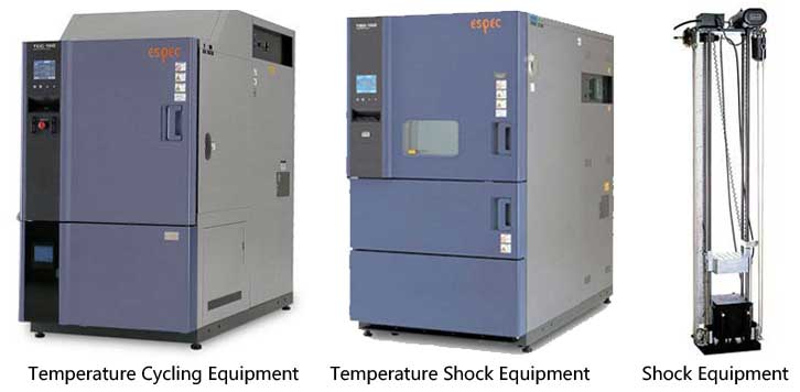
Temperature Cycling Tests (TCT): Temperature Cycling Test (TCT) is a crucial aspect of Board Level Reliability (BLR) testing, designed to evaluate thermal fatigue resistance. To replicate automotive conditions, TCT subjects components to cyclic temperature variations, typically ranging from -40°C to 125°C. This process tests the expansion and contraction of materials, aiming to identify solder joint cracks and delamination caused by thermal stress.
High failure rates during TCT often point to issues with Coefficient of Thermal Expansion (CTE) mismatches between materials. Each TCT cycle typically lasts around 30-60 minutes, with boards undergoing more than 1,000 cycles to validate their durability and ensure long-term reliability under harsh conditions.
- Thermal Shock Test (TST): TST exposes components to rapid temperature changes, ranging from -65°C to 150°C within 1 minute, simulating abrupt thermal transitions such as engine start-ups or cold starts. These fast temperature shifts induce thermal stresses that reveal weak interconnects and component-level vulnerabilities. Common defects identified through TST include microcracks in solder joints and degradation of packaging materials.
- Mechanical Shock Test: Mechanical shock testing replicates sudden forces experienced during vehicle collisions or impacts from potholes. Automotive parts are subjected to shocks of up to 1500g to simulate real-world impact scenarios. This test identifies potential solder joint failures and component detachments. Insights from the data aid in refining board designs to withstand extreme mechanical stresses, enhancing resilience in high-risk situations.
- Vibration Test: Vibration testing evaluates the fatigue resistance of electronic components under frequencies ranging from 10Hz to 2kHz. Automotive boards are subjected to sinusoidal and random vibrations to simulate conditions like engine idling or driving on rough terrain. Failures may include cracked solder joints, broken lead wires, or loose connectors. To meet automotive standards, components must endure hundreds of hours of testing at specified amplitudes.
- Flying Probe Test: Flying probe testing detects open circuits, shorts, and incorrect component placements in PCBs. Using fast-moving probes, it measures electrical continuity, capacitance, and resistance across the board. Unlike in-circuit testing, it does not require custom fixtures, making it ideal for prototypes and low-volume production. In automotive electronics, flying probe tests ensure high yields while detecting solder defects and connectivity issues early in the manufacturing process.
BLR Testing in Automotive Electronics and Packaging
Automotive Warpage Analysis
The increasing use of larger, thinner PCBs has made warpage analysis crucial for ensuring structural integrity and precise component assembly in automotive electronics. Warpage during reflow, caused by thermal imbalances in materials, directly impacts solder joint reliability. Advanced techniques such as shadow moiré and digital image correlation (DIC) enable highly accurate 3D surface measurements, revealing key deformations like package bending or twisting during heating cycles.
In lead-free soldering environments, tight warpage tolerances are critical to prevent issues like open joints, bridging, and misalignment during assembly. Since SMT reflow in lead-free processes requires higher temperatures (above 217°C, compared to 183°C for leaded solder), the risk of warpage increases significantly, making effective control even more essential.
Multi-Chip Modules (MCM) Testing
Multi-chip modules (MCMs) are thick, complex assemblies that require rigorous Board Level Reliability (BLR) testing to ensure performance under demanding automotive conditions. Thermal cycling tests subject automotive-grade MCMs to extreme temperature variations across numerous cycles, assessing durability against solder fatigue and delamination. Vibration testing further identifies potential connection issues. To ensure assembly cohesion over its lifespan, BLR testing for MCMs focuses on interposer integrity, die-attach reliability, and underfill behavior.
Advanced Packaging Technologies
Advanced packaging technologies, such as 3D ICs and Through-Silicon Vias (TSVs), introduce unique challenges for BLR testing due to their complex thermal and mechanical loads. For example, 3D ICs, which involve stacked dies, face concerns related to thermal dissipation and via-induced stress. Finite Element Analysis (FEA) models are essential for predicting fatigue failures in TSVs, as even minor warpage can lead to cracking.
What can iST do for you?
iST has built up relevant equipment capacity and integrating automotive IC and system to provide comprehensive reliability verification environment and meet “Board Level” customer requirements.

- Automotive board level