Issued Date:2021/2/24AEC-Q004
Issued By:iST
AEC-Q004
Preparing for the total recovery of the automotive industry in 2021, the global automotive supply chain is knocking on the door of local suppliers in Taiwan.
Facing these incredible business opportunities, are semiconductor manufacturers ready to tackle with the zero defects challenge?
AEC-Q004

The automotive semiconductor markets tanked in the first half of year 2020 as almost every country was locked in to fight the spread of the COVID-19 pandemic. Yet the supply and demand of the automotive industry bottomed out by the end of the same year. Amid low stock levels of automotive and regulations on autonomous cars getting unveiled by governments of individual nations, the market of automotive electronics is set to soar in 2021.
AEC-Q004
This is also the case with the semiconductor markets in Taiwan according to iST as global vehicle supply chains are visiting Taiwan to book capacity of foundries and learn about the local automotive component supply chains. Thanks to the fast penetration of electric cars, ADAS and autonomous cars, the demand for semiconductors is poised to soar. However, the design and manufacturing of automotive electronic products focus on “Design for Reliability” rather than on “Time to Market.”
Employing increasingly complex electronic systems in vehicles comes with a risk: the unexpected risks against drivers, passengers and neighboring cars and pedestrians caused by any function failures. Defects in automotive electronics not only may hamper personal safety but also come with huge costs of compensation and recall, which is hard to be borne by any enterprise. Therefore, reducing and preventing defects in electronic components becomes crucial.
To improve the quality and reliability of electronic products, the vehicle makers and tier 1 system suppliers mandated the defect rate of electronic components to go down below one part per billion (ppb). This has resulted in the adoption of zero defects in the supply chain of electronic products.
The Automotive Electronics Council (AEC) made a series of specifications on automotive electronics for the concerned supply chains to meet the requirements of zero defects (please refer to “Six Key points to Learn the AEC-Q104 for Automotive MCM in No Time). Addressing zero defects, the first edition of AEC-Q004 guidelines has been released in 2020. This is a handbook aimed to supplement the specifications of AEC-Q100 (IC chips), AEC-Q101 (discrete components), AEC-Q102 (discrete photoelectric component), AEC-Q103 (MEMS), AEC-Q104 (multichip module) and AEC-Q200 (passive components).
This iST Tech Classroom is aimed to present you with a detailed introduction on the basic concepts of AEC-Q004 and the six tools for zero defects.
1. Basic Concepts
The AEC-Q004 guidelines contain a strategy structure over zero defects (see Figure 1). It is aimed to implement the industry’s best processes, methods and tools, or error screening steps exclusive to individual component suppliers in stages of process design,product design,production and product/manufacturing improvement to reduce defects.
It may be applied with semiconductor products compliant with the specifications for AEC-Q100 (IC chips), AEC-Q101 (discrete components), AEC-Q102 (discrete optoelectronic components), AEC-Q103 (MEMS), AEC-Q104 (multichip modules) and AEC-Q200 (passive components).
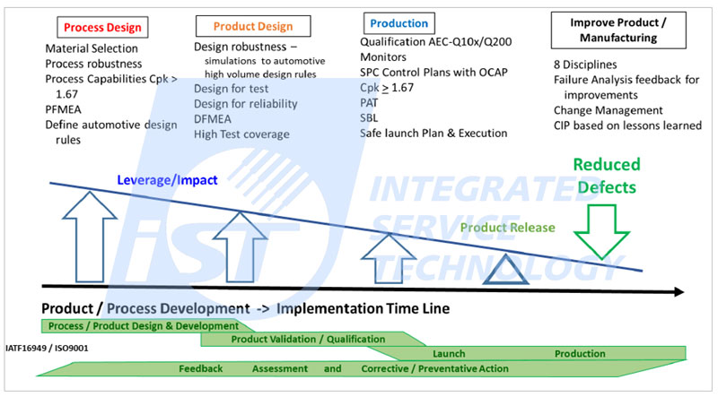
Figure 1: Automotive Zero Defects Framework (Source: AEC-Q004)
2. Application of Zero Defects Structure
Semiconductor suppliers may adopt tools contained in this structure to identify, reduce and eliminate defects. They may work with semiconductor component users to select and combine tools provided to meet the expectations and requirements on products set by customers under the considerations of effectiveness, ease of use, availability and costs.
This structure contains six key elements (see Figure 2):
- Product Design
- Manufacturing
- Test
- Application and Capability
- Continuous Improvement Methods
- Problem Solving
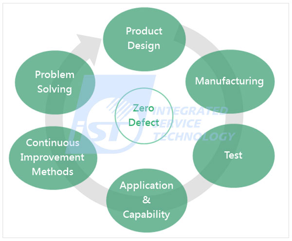
Figure 2: The six key elements of zero defects structure
They are aimed to remove defects of electronic components at the stages of development and design, manufacturing, test, product application, improve methods, and problem solving. See below for an outline of each tool.
I. Product Design
1. Design Failure Mode and Effect Analysis (DFMEA)
DFMEA is aimed to identify failure modes in the design stage and their impact on product system and application, assess risk index (including Severity, Occurrence and Detection, determine real causes and take the required control measures. It is also the five core tools of IATF 16949.
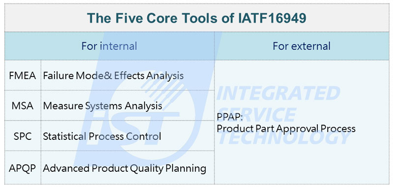
Figure 3: The five core tools of IATF 16949
2. Redundancy
This is a parallel backup system with the same functionality and equal performance, which could seamlessly replace faulty ones to increase the system’s mean time to failure.
3. Built-in Self-Test (BIST)
This is a technology to add BIST in ICs especially for highly complex components. This involves testing of their own operation (functionally, parametrically, or both) by using their own circuits to mitigate reliance on external Automatic Test Equipment (ATE), cut test costs and reduce Time to Market (TTM).
4. Design for Test
This is aimed to test the maximum number of nodes of highly complex components in a reasonable amount of time to maximize the fault coverage rate in the test period. In short, this is to test and identify unnoticed or potential failures through test programs before mass production. The higher the fault coverage is, the fewer IC bugs will occur.
5. Design for Analysis
To avoid not being able to find defects, starting from the circuit design stage, direct observation and control of embedded and underlying circuits should be allowed in order to find faulty circuits and perform physical failure analysis (PFA).
6. Design for Manufacturability
With larger design margins in circuitry, the manufacturing of parts becomes more repeatable and reproducible. In this way, it can mitigate the impact of process defects on products and improve product yield and quality.
7. Design for Reliability
This is aimed to estimate the reliability lifetime of components and preventing reliability issues through optimizing circuit, layout or structure without sacrificing performance.
8. Simulation and Modeling
Simulation is a method to model the device functionality and reliability performance of the finished product or part of it, which uses process element models, package physical and materials models, and design guidelines to validate the product functionality and performance over lifetime. Simulations can provide orders of magnitude larger parametric variation than validation on actual products only
9. Characterization
Learn about process attributes, performance and constraints of components to create the process specification limit and datasheet of the product by reviewing the parameter characteristics including temperature, voltage, frequency and safety mechanism of components. This also complies with the functional safety request of product set in ISO 26262.
II. Manufacturing
1. Process Failure Mode and Effect Analysis (PFMEA)
PFMEA is aimed to identify failure modes in the manufacturing stage and their impact on product system and application, assess risk index (including Severity, Occurrence and Detection, determine real causes and take the required control measures. It is also the five core tools of IATF 16949.
2. Statistical Analysis of Variance
Analyze statistics of process variables (e.g., process parameter) to correlate with electrical or other parameters of the product. Variances contained in the data could be systematic and random. We can balance process parameters or product characteristics with this method to get the optimum yield, function and reliability.
3. Control Plan
These outline product/process characteristics and relevant process variables to ensure the products’ compliance with the target or standard values while maintaining reliability along the passing of time. For example, Cpk is a method used to measure stability in a control plan which contains actions to be taken in case of deviation, e.g., Out of Control Action Plan (OCAP).
4. Statistical Process Control
This is also known as SPC and is aimed to monitor production process, collect data, identify process error, determine causes of the variances and come up with solutions for immediate process improvement with control charts, process capacity analysis (Ca, Cp, Cpk) and other statistical methods. All these are aimed to maintain the stability of quality and parameters.
5. Lot Acceptance Gates
Perform sampling tests on batches of finished products to determine whether the batches are suitable for further manufacturing or shipment to customers.
6. Audits-Management System, Manufacturing Process and Product
Check or review whether the manufacturers comply with IATF 16949 and other automotive industry standards to ensure the maintenance, development and improvement of the quality management system, manufacturing process and product inspection related specifications.
III. Test
1. Part Average TestingAEC-Q004
This is a system aimed for design, analysis, manufacturing control and parameter test ( both electrical and physical) to monitor quality. It enhances reliability by using stringent specifications to provide better quality. That is, a statistical method removes outliers from a given product population (See Figure 4).
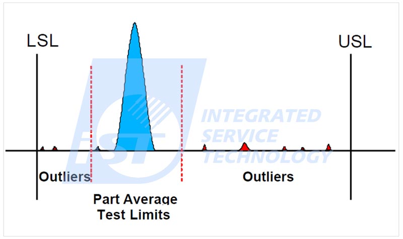
Figure 4: Guidelines for Parts Average Testing (Source: AEC-Q001)
2. Statistical Bin Yield Analysis
A system for analyzing measurements of test parameters/bins with the goal of reducing variation and detecting latent defectivity.
3. Data Collection, Storage and Retrieval
This covers the measurement, storage, archiving and retrieval of data when dealing with relevant issues of reliability and product manufacture. Rapid availability of data will speed up containment of issues, lead to continuous improvement activities, and allow rapid risk assessment. Benchmark for quality improvement.AEC-Q004
4. Screens
Test screens are tools to guard band device performance and reliability robustness against any defect induced failure mechanism.
IV. Application and Capability
1. Industry Standards
Provide standard methods of testing that is applicable for both Suppliers and Users and offer benchmarks of performance that can be applied across many devices, processes and materials.
2. Environmental Stress Testing
Reliability Design Test aims to identify vulnerability in the design, process and packaging to ensure products meet the requirements of quality and reliability set by suppliers and users. It employs physical, mechanical, electrical or environmental accelerated stress tests on products to identify latent defects earlier.
3. Stress-Strength Analysis
Stress-Strength Analysis is a method that uses test-to-fail principles and the analysis of the failure distribution data. It helps determine the design or process margin for a given application.AEC-Q004
4. Systems Engineering
This method is intended to align the system design with User application. The practice of systems engineering involves translating User needs into system requirements that can then be realized through architecture and design. To achieve the goal of zero defects, you have to take a system-level structure along with Design for Reliability (DfR), Design for Manufacturability (DfM) and Design for Test (DfT) into account to ensure compliance of product specifications and verification plan with the system requirements at the early stage of development. In addition, products with Functional Safety requirements have defined standards containing system engineering, e.g., ISO 26262 V model (see Figure 5) to meet the acceptance level of Fault Metric and Diagnostic Coverage for Automotive Safety Integrity Level (ASIL) relevant to functional safety design.
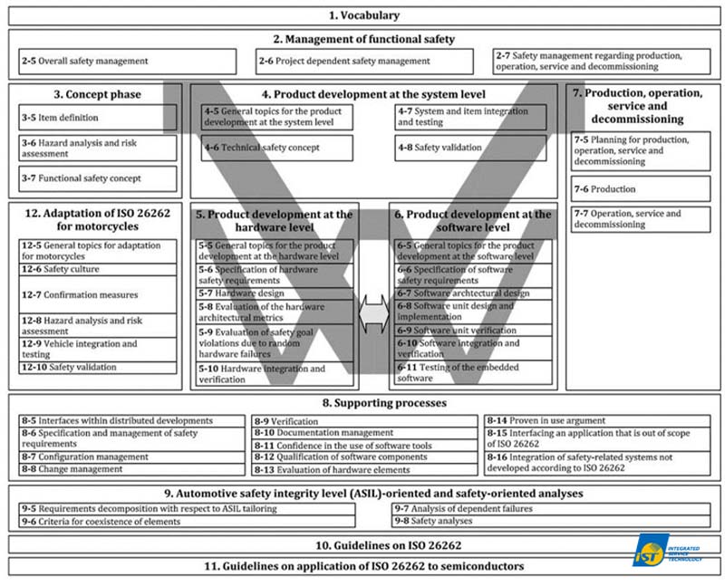
Figure 5: V model (Source: ISO 26262: 2018)
5. Product Derating
The practice of using a product in a narrower environmental and/or operating envelope than its Manufacturer/Supplier designated limits. This reduces electrical, thermal and mechanical stress exerted on the components to a level better than the rated values to extend their life span and raise their reliability to prevent them from unexpected application anomalies.
V. Continuous Improvement Methods
1. Wafer Level Process Monitoring
This is aimed to quickly identify specific failure mechanisms (e.g., TDDB, HCI, BTI, and EM) at the early stages of manufacturing. Benefits may include early detection of potential problems (defective wafers or lots can be repaired or scrapped), analysis and control of specific failure mechanisms and providing a statistical basis for analysis and screening.AEC-Q004
2. Process and Product Improvements
Change in material or process or embedded software (firmware), either to address a root cause issue or as an evolution of a process or design, to improve product function, yield and/or reliability. Attention should be paid to change control and risk management (e.g., FMEA update).
3. Product Reliability Monitoring
This requires periodic reliability testing of a sample of representative products or test vehicles with the purpose of monitoring whether a process excursion occurred to create a defect. Countermeasures should be proposed to mitigate risks of product failure in later production.AEC-Q004
4. Defect Monitoring
Achieving zero defects is dependent upon the combined efforts of all Suppliers at the semiconductor product level. Detecting defects through monitoring and eliminating them before they are incorporated into any finished goods is key to any successful zero defects program. The occurrence of defects may be related to process, equipment, environment and personnel. Defect monitoring is to review or check the quality of production materials in every key stage throughout the entire production flow by electrical measurement and visual inspection. This is the way to get better yield and reliability, reduce the field failure rate at earlier stage and prevent minor anomalies from developing into major issues.
VI. Problem Solving
1. Problem Solving Techniques
This is aimed to identify root cause, contain and correct the problem, verify the problem is understood and solved, and prevent its recurrence. It is also used as a reporting tool to document the issue for a User (e.g., 8D reports, fishbone and fault tree analysis).
2. Failure Analysis Process
When a failure occurs within all tiers of automotive manufacturing or in the field, a User may request Failure Analysis (FA) of its Supplier. This requires collecting and analyzing a huge amount of data, identifying specific causes to failure and taking corresponding containment and corrective measures to prevent it from occurring again. The analysis process starts with non-destructive Electrical Failure Analysis (EFA) and followed by Physical Failure Analysis (PFA) once the cause of the failure has been identified.
3. Conclusion
Compared with the past, in today’s automotive engineering environment, semiconductor components and highly complex systems are interdependent, and each vehicle is technologically more advanced. Therefore, reducing defects is an extremely important goal for all manufacturers, but the adoption of the “Zero Defect Program” could significantly raise the threshold of technology, quality, and cost.
Zero defect is a prevention-oriented concept. Adopting it mandates changes in the operating and theoretical model. The system has to morph from units relying on independent operations and rare communication into a cross-units network so as to link and share information and deal with issues in a more comprehensive manner.
iST recommend suppliers endeavoring to zero defects to not only comply with the AEC-Q series specifications but also meet the requirements of functional safety set by ISO 26262 in the design stage and IATF 16949 in the production stage to reduce variance in quality. iST is very experienced in reliability verification and quality system consultancy for automotive electronics.
For automotive electronics verification inquiries:
Please call us at +886-3-579-9909 Ext. 6403 Ms. Wu or email us at WEB_RCE@istgroup.com
For quality system certification consultancy inquiries:
Please call Mr. Lin at Ext. 8807 or email him at WEB_ISD@istgroup.com