Various temperature conditions can expose product vulnerabilities, leading to damage or failure and compromising reliability. Thermal cycling and shock testing simulate extreme temperature variations to identify issues like cracking, deformation, or material fatigue. Widely applied in aerospace, electronics, and automotive industries, these tests ensure components withstand operational stresses and maintain durability throughout their life cycle.
What can iST do for you?
- Thermal Cycling: Conduct high-low temperature cycling tests with a temperature change rate less than 20°C per minute.
- Thermal Shock: Expose DUTs to extreme temperature conditions with a change rate of 30–60°C per minute, or even faster.
This test does not mimic actual environment construction. Instead, it is applying harsh stress and accelerated aging factors to DUTs to identify potential causes which may lead to system equipment and components failure to validate product design or manufacturing.

Thermal Cycling Testing vs. Thermal Shock Testing
This table summarizes the differences between Thermal Shock and Thermal Cycling Testing.
| Aspect | Thermal Cycling Testing (TCT) | Thermal Shock Testing (TST) |
| Purpose | Identifies failures due to mismatches in the coefficient of thermal expansion (CTE) between materials and tests a device's ability to endure repeated extreme temperature changes. | Determine the resistance of a part to sudden exposure to extreme changes in temperature and to the effect of alternate exposures to these extremes. |
| Test Environment | Single chamber where temperature shifts between high and low extremes. | Multiple chambers (hot and cold) or rapid transition setups, including air-to-air or liquid-to-liquid. |
| Failure Mechanisms Detected | - Solder joint cracking | - Wire breaks |
| - Lead/terminal damages | - Wire bond lifting | |
| - Hermetic seal failures | - Flip-chip bump failures | |
| - Delaminations in PCBs | - Die cracking | |
| - BGA interconnect defects | - Package cracking | |
| Inspection and Testing | Detects long-term reliability issues due to Temperature cycling. | Post-test includes visual inspection and electrical testing for overstress failures. |
| Rate of Temperature Change | Gradual, over a longer period. | Immediate, within seconds. |
| Typical Failure Types | - Shear creep fatigue | - Tensile overstressed |
| - Stress relaxation | - Tensile fatigue | |
| Reference Specification |
|
|
Normal Failure mode
- Solder cracks due to big difference in material expansion coefficient
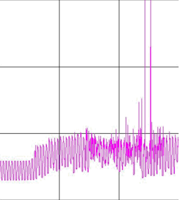
- Resistance value errors
The Superiority of iST
- Large capacity of Temperature cycling chambers in Asia
- Provide customers up to 70,000 channels for online monitoring
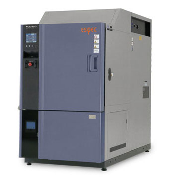
Temperature cyclic Chamber
- Consumer IC/automotive board level