Issued Date:2024/09/05
Issued By:iST
Is there a way to prevent a PCB, assembled with flawless IC chips, from failing due to poor soldering?
IC design houses thoroughly test the quality of their IC products, yet a PCB assembled with perfect IC components can still fail in certain situations. This not only wastes time and money but also incurs additional costs for rework and retesting. The root cause often lies in the IC component makers’ limited understanding of the packaging and bonding processes that occur at OSATs (Outsourced Semiconductor Assembly and Test providers) or system integrators. Without this insight, they struggle to meet the technical requirements of PCB manufacturing. This is where Board Level Reliability (BLR) comes into play, ensuring that IC components are better suited to their application environments.
BLR
Understanding Board Level Test (BLR)
Board level reliability (BLR), Board Level also known as L2 or Level 2,tests L1-packaged ICs on PCBs. BLR evaluates the reliability of solder joints for IC components mounted on PCBs. This test is crucial for ensuring component functionality within their intended application. See the following figure for an illustration.
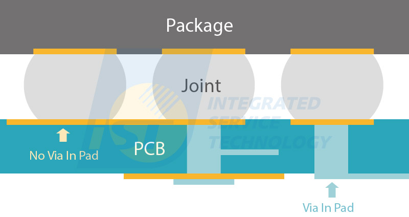
Figure 1 : Illustration for package IC components mounted on PCBs
BLR is a standard verification test widely used in the consumer electronics industry and has been employed by iST labs for years. As vehicle electronic systems become more complex, BLR has also become a critical requirement for automotive electronics. This test helps IC components fit their application environment more closely, preventing failures due to poor soldering.
Differences Between Consumer and Automotive Electronic Board Level Tests
BLR Verification for Consumer Electronics
Consumer electronics are becoming increasingly complex, driving the need for a variety of IC chips. For example, cellphones now require the integration of more advanced chips, leading to advancements in IC packaging technology. To ensure quality, top consumer brands are urging IC chip suppliers to conduct Board Level Reliability (BLR) tests. Critical items tested for IC-mounted PCBs in cellphones include mechanical and environmental stress, such as drop tests and temperature cycle tests (TCT).
For consumer products, board-level reliability can be assessed using international standards such as JEDEC B102, B103, A104, B111, B113, and IPC-9701~ 9704 and 9708. Additionally, major consumer brand companies often have their own specific customer requirements
BLR Verification for Automotive Electronics
As automotive electronic systems become increasingly complex, the demand for rigorous Board Level Reliability (BLR) verification has intensified. This testing is required by car manufacturers and Tier 1 suppliers such as BOSCH, Continental, and TRW. The Automotive Electronics Council (AEC) has defined specific BLR tests in its AEC-Q104 and AEC-Q007 specifications.
Compared to the AEC-Q104 standard, which only briefly mentions BLR in Test Group H and lacks detailed guidelines for PCB and Daisy Chain design, the AEC-Q007 standard takes a more comprehensive approach. It explicitly addresses PCBs by incorporating BLR verification methods to monitor solder joint failures. Beyond outlining testing methods, AEC-Q007 also provides detailed recommendations for PCB and Daisy Chain designs, ensuring a more thorough approach to BLR in automotive applications.
(Read more: Enter the Supply Chain of EV in Five Steps: An analysis of International Automotive Reliability Specs and The Latest AEC-Q007 Specification Unveils Advanced Board Level Verification for Automotive Applications)
Can We Apply the BLR Test Conditions Used for Consumer Electronics to Automotive Electronics?
The answer is no. Automotive electronic modules operate in very different environments compared to consumer electronics. Components in vehicles are subjected to constant vibration, mechanical stress, and harsh conditions that consumer product specifications cannot withstand. See Table 1 for a comparison of JEDEC and AEC-Q specifications versus popular consumer electronics specifications.
Comparison of JEDEC, AEC-Q, and popular consumer electronics specifications Test Item A Company B Company C Company AEC-Q104 JEDEC RTC -40~125℃ @ 2,000cyc~4,000cyc, 30 mins. dwell time, Dual chamber (Air to Air) -40~125℃, @2,000 cyc, 10 mins. dwell time, 10 ≤ ∆T/∆t ≤ 20 K/min. -40~85℃/-40~125℃ @3,000cyc, 10 mins. dwell times, 30 mins transfer time Follow IPC-9701, Based on intended use environment, -40~125℃, 1,000cyc Based on the intended use environment PTC -40~105℃ @ 2,600 cyc., T on/off =5mins, 10mins./cyc. NA NA -40~85℃, -40~125℃, T on/off = 20 or 30mins., 60 or 80mins./cyc. NA Vibration 100Hz~2,000Hz @ 5.02 PSD, RMS acceleration: 97.7m/s2., Random Vibration + Temp., Real chip 20Hz~2,000Hz @ 0.1 PSD, RMS acceleration: 189.4~818m/s2., Sine sweep or random VIB NA NA 20Hz~2,000Hz, sine or random Drop NA Direction C+/C-: 1,000G, 1.4ms Direction C-: 1,500G, 0.5ms, 60 drop Direction C-: 1,500G, 0.5ms, 30 drop Direction C-: 1,500G, 0.5ms, 30 drop Bending Deflection d=1mm, 20sec, Bend to fail NA Displacement d=2.0mm, 100cyc., Displacement d=4.0mm, 100cyc. NA Deflection d=2mm, 200k times or Bend to fail How to Perform a Board Level Test
iST provides comprehensive BLR test services from designing and fabricating test boards to tests performing and failure analysis. Performing a Board Level Test involves several key steps:
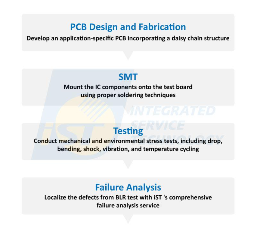
Figure 2: Steps for BLR test.
Step 1:PCB Design and Fabrication
To accurately assess the solderability of PCB-mounted components, the BLR test involves designing an application-specific test board with a daisy chain structure. This setup creates a grid between each solder joint and the PCB, allowing for real-time monitoring of joint performance and immediate failure diagnosis. This enables quick identification of issues and implementation of improvements.
To further enhance testing accuracy and prevent unexpected situations, iST provides both JEDEC/IPC-compliant PCBs and customizable PCBs tailored to simulate the conditions of your system integrators.
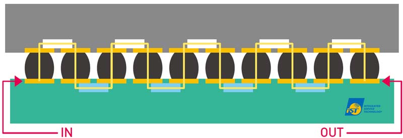
Figure 3: Daisy chain design
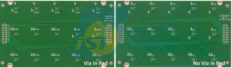
Figure 4: JEDEC/IPC specification compliant test PCB provided by iST
Step 2: Surface Mounting IC Components
Mount IC components onto the PCB test board using proper soldering techniques. The accuracy of the product’s life cycle depends on the quality of mounting, including types of solder paste, demolding space, demolding time, printing speed, accuracy of component insertion position and selection of steel plate. After SMT, X-ray or ultrasonic tests are conducted to assess reflow quality.
According to iST’s experience, instead of relying on inadequate BLR verification and incurring unnecessary costs, simulating component and PCB warpage before selecting SMT settings improves reliability and soldering yield. Warpage measurement analysis takes about an hour and aids, supports BLR testing by helping to develop preventive measures and improvements. (Read more: Count Warpage Amount Before SMT to Avoid Solder Empty and Early Failure)
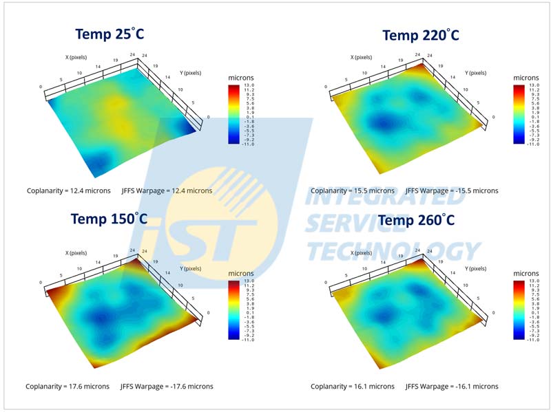
Figure 5: Simulating a temperature cycling environment to identify the temperature that causes the most severe deformation
Step 3:Running BLR Tests
Conduct mechanical and environmental stress testings. The BLR test uses low and high strain rates. Low strain rate tests, like the Temperature Cycle Test(TCT) and Bending test, assess durability under gradual and mild variations. High strain rate tests, including Mechanical Shock and Vibration, evaluate resilience under more extreme conditions.
Step 4:Failure Analysis
Analyze the results for solder joint or IC component failures. The BLR component-mounted test board with failed joints should undergocomprehensive failure analysis using methods such as X-ray, SAT, Thermal EMMI, Dye and Pry, and Cross-section methods. It helps identify faults and facilitates speedy re-verification for market introduction.
Common failures identified after BLR tests include:
- Solder Joint Cracking: Repeated temperature changes can cause solder joints to experience thermal fatigue, leading to the formation of cracks and eventual circuit failure.
- Material fatigue : Structural components or materials may undergo fatigue after numerous temperature cycles, resulting in reduced strength or crack formation.
- Thermal expansion mismatch: Different materials have varying coefficients of thermal expansion, which can lead to stress during temperature cycling, causing cracks or separation at material interfaces.
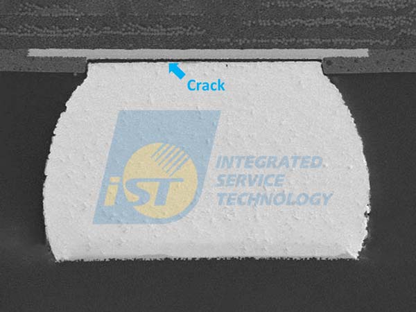
Figure 6: Cross-section of samples subjected to high-speed mechanical impact, revealing a crack at the solder ball joint (indicated by the blue arrow)
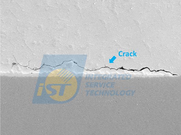
Figure 7: Cross-section of samples exposed to prolonged temperature cycling, showing the presence of cracks (indicated by the blue arrow)
Common Concerns after Board Level Tests
Here are three frequently asked questions in recent years.
What does a 1,000 temperature cycle test mean for my product?
A 1,000 cycle test is equivalent to 1,000 days, or nearly three years of operation. If your product passes this test, it suggests that it is likely to function reliably under normal application conditions for at least 2-3 years without defects.
Which condition should I select for the mechanical impact (drop) test of BLR?
The drop test conditions vary depending on the type of product. For example, the drop height for a cellphone differs from that of a computer or tablet. Specifically, for a cellphone, the drop test height is 112 cm, and you should select Condition “B,” which is 1,500G at 0.5ms, as shown in Table 2.
Conditions for drop test Service Condition Acceleration Peak Pulse duration Velocity Change Equivalent Drop height H 2900 g 0.3 ms 543 cm/s 214 in/s 150 cm 59 inches G 2000 g 0.4 ms 499 cm/s 197 in/s 127 cm 50 inches B 1500 g 0.5 ms 468 cm/s 184 in/s 112 cm 44 inches F 900 g 0.7 ms 393 cm/s 155 in/s 78.9 cm 31 inches A 500 g 1 ms 312 cm/s 123 in/s 49.7 cm 20 inches E 340 g 1.2 ms 255 cm/s 100 in/s 33.1 cm 13 inches D 200 g 1.5 ms 187 cm/s 73.7 in/s 17.9 cm 7 inches C 100 g 2 ms 125 cm/s 49.2 in/s 7.9 cm 3 inches How to estimate the service life of my product based on BLR test data?
After long-term testing, failure data from a certain number of samples can be obtained. By further using Weibull analysis to estimate the characteristic life (η) of the product, one can assess whether the product can withstand reliability verification or has achieved a sufficiently reliable service life, whether during the product verification stage or in R&D.
Take Figure 8 as an example: the vertical axis represents the failure percentage, while the horizontal axis represents the testing time. Under the same testing environment and duration, a significant difference in the characteristic life by 2,000 cycles is evident. Simply changing one material resulted in such a substantial change, demonstrating the critical importance of material selection and application in reliability testing. Even a slight difference early on can lead to significant discrepancies later in the process.
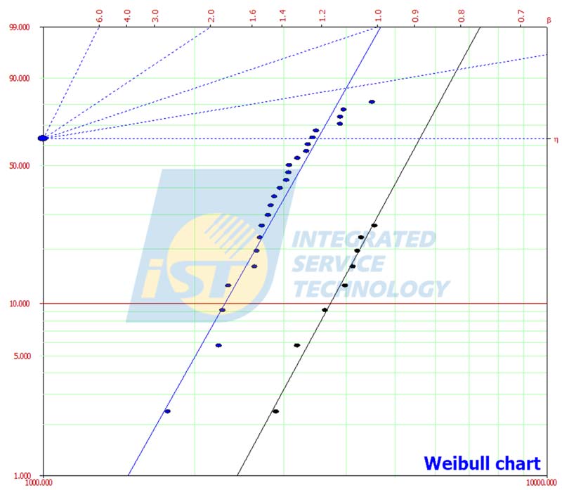
Figure 8: Material 1 (blue line): η = 3,506 cycles; material 2 (black line): η = 5,586 cycles
Board Level Tests are essential for ensuring the reliability of IC components mounted on PCBs. By understanding and implementing these tests, IC design engineers can prevent failures, reduce costs, and meet industry standards. For more information or to discuss your BLR testing needs, please contact Mr. Chen at +886-3-579-9909 Ext. 6418 or email web_BLR@istgroup.com.
Other services you may be interested in
BLR