
Issued Date: 2021/4/20Automotive Reliability
Issued By: iST
Achieving high reliability in automotive electronics takes more than having an IC pass AEC-Q qualification. From soldering a component onto a PCB to assembling a complete module and installing it in a vehicle, each stage can introduce new reliability risks. The key is to progressively verify the reliability of the components, PCB, solder joints, assembly, and ultimately, the complete system.
Automotive Reliability

Vehicle performance is closely tied to road safety. As a result, original equipment manufacturers (OEMs) and Tier 1 suppliers impose stricter quality and reliability requirements on electronic components than those typically applied to consumer electronics. Automotive electronics reliability must therefore be verified throughout the supply chain—from components and PCBs to solder joints, assembled boards, and complete systems.
This article explains how automotive electronics reliability is established step by step across five levels: Component, PCB, Board, PCBA, and System.
I. Why Use the V-Model for Automotive Electronics Validation?
The V-model (Figure 1) provides a useful framework for understanding automotive electronics development and validation. On the left side, vehicle-level requirements are progressively broken down into system, electronic control unit (ECU), and component requirements. On the right side, validation proceeds in the opposite direction, starting with individual components and working upward to the complete system and vehicle-level requirements.
Simply put, requirements are defined from the top down, while reliability is validated from the bottom up.This approach helps engineers trace product failures to the appropriate level—whether the cause lies in a component, PCB, solder joint, assembly process, system design, or actual operating environment. It allows potential problems to be identified before a complete system fails testing.
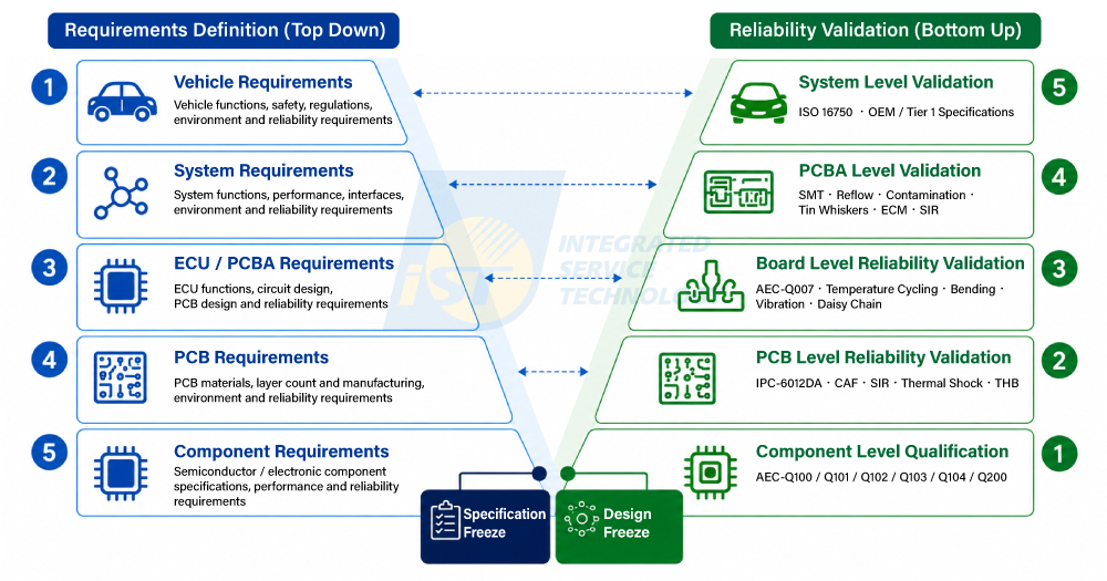
Figure 1: V-model framework for automotive electronics, from requirements definition to reliability validation
(Source: Compiled by iST; concept based on SAE J1211)Table 1: Five-Level Reliability Validation Framework
Validation Level Main Objects of Validation Key Question Common Standards / Methods Step 1: Component Level ICs, discrete semiconductors, MEMS, multi-chip modules (MCMs), and passive components Are the components themselves reliable? AEC-Q100 / Q101 / Q102 / Q103 / Q104 / Q200, etc. Step 2: PCB Level Printed circuit boards Are the board materials, vias, insulation, and structure reliable? IPC-6012DA, CAF, SIR, etc. Step 3: Board Level Components, PCB, and solder joints Are the components reliable after being mounted on the PCB? AEC-Q007, BLR Step 4: PCBA Level Fully assembled PCB assemblies Do SMT, materials, or assembly processes introduce new risks? SIR, ECM, HALT, and testing tailored to product requirements Step 5: System Level ECUs / electronic modules Can the integrated product withstand its actual in-vehicle environment? ISO 16750, OEM / Tier 1 customer-specific requirements II. Why Must Automotive Electronics Reliability Validation Go Beyond Individual Components?
Automotive electronics may be exposed to prolonged environmental stresses, including high and low temperatures, moisture, temperature cycling, vibration, mechanical shock, and electrical loads. Once components are mounted on a PCB and assembled into a module, solder joints, material interfaces, and assembly processes can introduce additional failure mechanisms.
Automotive reliability must therefore address more than whether an individual IC will last. It must also establish whether the product remains reliable after board mounting, after assembly, and ultimately, in its actual in-vehicle operating environment.
Validating reliability from the component level through the system level helps identify potential failure risks involving components, materials, processes, and system interactions during product development.
III. Five Steps to Validate Automotive Electronics Reliability
Step 1 | Component Level: How Does AEC-Q Evaluate Automotive Electronic Component Reliability?
The first step focuses on the components themselves.
The Automotive Electronics Council (AEC) has established reliability qualification standards for different types of automotive electronic components. For example, AEC-Q100 applies to ICs, AEC-Q101 to discrete semiconductors, AEC-Q102 to discrete optoelectronic semiconductors, AEC-Q103 to MEMS devices, AEC-Q104 to MCMs, and AEC-Q200 to passive components.
The AEC-Q series evaluates component reliability under intended automotive conditions through a range of environmental, life, electrical, and package-related reliability tests.
Passing component-level qualification is only the first step.
Once a component is soldered onto a PCB, PCB materials, solder joints, the surface-mount technology (SMT) process, and differences in the coefficient of thermal expansion (CTE) between materials can introduce new reliability risks.
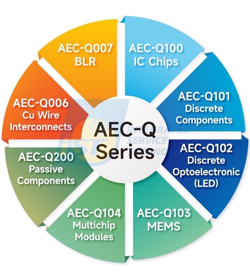
Figure 2: AEC-Q standards applicable to automotive semiconductors
(Source: iST)Step 2 | PCB Level: Why Can the PCB Cause Product Failure Even When All ICs Are Reliable?
A printed circuit board (PCB) provides the essential platform for interconnecting semiconductors, passive components, and other electronic parts. If the PCB develops problems with electrical continuity, insulation, or material reliability, the entire ECU or electronic module may fail—even when every IC meets component-level reliability requirements.
Depending on product and customer requirements, automotive PCB reliability can be evaluated with reference to IPC-6012 and other relevant standards. Common tests include:
- Reflow thermal stress testing
- Thermal shock endurance testing
- High-temperature endurance testing
- High-temperature and humidity storage testing
- Conductive anodic filament (CAF) testing
- Surface insulation resistance (SIR) testing
For automotive PCBs, material selection, stack-up, via structure, surface finish, and manufacturing quality can all affect long-term reliability.
PCB-level validation therefore asks “whether the bare board itself is reliable". PCBA-level validation subsequently examines "whether SMT and assembly have introduced risks that were not present in the bare board".Step 3 | Board Level: Evaluating Solder Joint Interconnect Reliability After Component Mounting
A component and PCB may each pass their respective reliability assessments, but this does not guarantee reliability once the component is soldered onto the board.
The package, PCB, and solder have different coefficients of thermal expansion. As automotive electronics repeatedly heat up and cool down, these materials expand and contract by different amounts. Over time, the resulting thermomechanical stresses can cause fatigue cracks in solder joints.
This is the issue addressed by board level reliability (BLR) testing.AEC released AEC-Q007 in 2024, providing further guidance for automotive BLR qualification. It incorporates components, PCBs, and daisy-chain test interface designs into the evaluation. Monitoring changes in daisy-chain resistance during temperature cycling helps detect changes in interconnect integrity. Failure analysis can then identify the solder joint failure locations and mechanisms.
However, AEC-Q007 does not encompass every automotive BLR requirement. Depending on the product’s mission profile and OEM / Tier 1 requirements, additional evaluation may include vibration, mechanical shock, or other mechanical and environmental stresses. iST’s BLR services also cover combined vibration testing, thermal shock testing, and related stress tests.
Daisy-chain designs and resistance monitoring reveal electrical changes and failures in interconnect structures during temperature cycling. Combined with failure analysis, these methods help determine solder joint failure locations and mechanisms, providing an important basis for assessing automotive board-level reliability life. (Read more: AEC-Q007 Automotive Board Level Reliability Qualification)
Table 2: AEC-Q007 and Broader Automotive BLR / Tier 1 Requirements
Evaluation Item AEC-Q007 Broader Automotive BLR / Customer Specifications Temperature cycling Core test Commonly required Daisy-chain monitoring Key method Commonly used Solder joint thermal fatigue life Core evaluation objective Commonly evaluated Vibration Currently outside the core requirements Evaluated according to product / Tier 1 requirements Mechanical shock Currently outside the core requirements Evaluated according to product / Tier 1 requirements Drop Not applicable to every automotive product Determined by product / customer specifications Bending Outside the core scope of AEC-Q007 Determined by product / customer specifications Failure analysis Recommended as a complementary assessment Important Table 3: Customers in Previous iST Laboratory Projects
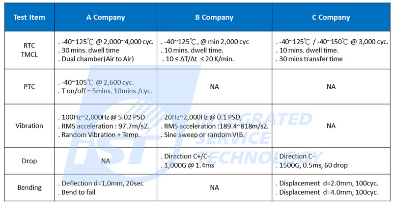
Actual test items and conditions vary according to the product application, mission profile, and OEM / Tier 1 customer-specific requirements. This table presents case examples only and does not represent standard AEC-Q007 test conditions.
Five Common Factors Affecting Automotive BLR Solder Joint Reliability
Based on experience at iST and DEKRA iST laboratories, five major factors commonly affect the board-level solder joint reliability of automotive chips:
- Solder joint size and layout
- Solder alloy composition
- PCB design and material selection
- Reflow process and flux residues
- Materials surrounding solder joints, such as underfill
Differences in the coefficient of thermal expansion (CTE) between the package, PCB, and solder deserve particular attention.
As automotive electronics repeatedly heat up and cool down, different materials expand and contract by different amounts. Solder joints may consequently experience prolonged tensile, compressive, and shear stresses, eventually developing fatigue cracks or other failures.
Automotive chips may have an expected service life of more than 10 years, making careful evaluation of test conditions essential. BLR considerations should therefore be incorporated into package, PCB, and material design, rather than deferred until product development is complete. Addressing potential reliability risks early can shorten corrective-action timelines and reduce the costs associated with subsequent failure analysis and improvements.
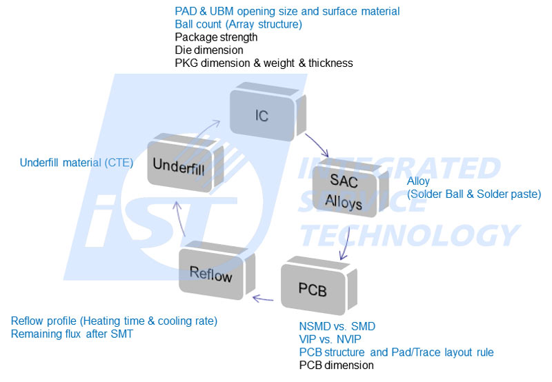
Figure 3: Five key factors affecting board-level solder joint reliability in automotive electronics
(Source: iST)Step 4 | PCBA Level: Why Can an Assembled Board Fail Even When Its Solder Joints Are Reliable?
Even when semiconductor components, PCBs, and solder joints have passed their respective reliability assessments, SMT, reflow, and assembly processes can introduce new risks. These may arise from flux residues, ionic contamination, material compatibility, or process conditions.
PCBA-level validation therefore extends beyond individual solder joint reliability. It examines whether the materials and processes used in the fully assembled board could lead to leakage, corrosion, electrochemical migration (ECM), or other potential failures during long-term operation.
Based on iST and DEKRA iST laboratories’ experience serving international Tier 1 customers, PCBA reliability validation requirements can vary across applications. These include in-vehicle information systems and ECUs associated with vehicle safety functions, such as anti-lock braking systems (ABS) and supplemental restraint systems (SRS).
It is worth noting that,“no single set of automotive PCBA test conditions applies to every product”. OEMs and Tier 1 suppliers typically develop reliability test plans according to the product application, mission profile, expected service life, and customer-specific requirements (CSR). Common evaluation includes:
- Surface Insulation Resistance (SIR)
Temperature, humidity, and electrical bias conditions are used to evaluate whether surface contamination or process residues on the PCBA degrade insulation performance. - Electrochemical Migration (ECM)
Under the combined effects of moisture, ionic contamination, and an electric field, conductive metals may migrate, creating a risk of leakage or even short circuits. - Ionic Contamination and Process Cleanliness
Flux or other ionic residues remaining after SMT and reflow may increase the risk of corrosion, leakage, and ECM under high-temperature and high-humidity conditions. - Tin Whiskers and Material Reliability
Depending on the materials and processes used, testing may assess tin whiskers and other material-related risks that could affect long-term reliability.The focus of PCBA-level reliability validation goes beyond solder joint strength. It determines whether the assembly process and materials have introduced risks that could cause future failures.
An appropriate test plan should therefore be developed according to the operating environment, mission profile, and customer requirements to identify potential failure mechanisms associated with assembly processes and materials at an early stage.
Step 5 | System Level: Why Test the Complete System After the First Four Levels Have Passed?
Reliable individual parts do not automatically guarantee a reliable complete system.
Once components, PCBs, and PCBAs are integrated into an ECU or complete electronic module, the installation location, electrical loads, thermal management conditions, vibration, temperature, humidity, and chemical exposure can introduce additional system-level risks.
System-level test plans can be developed with reference to ISO 16750 and OEM / Tier 1 customer-specific requirements, depending on the product type, installation location, and customer requirements.
ISO 16750 addresses a range of environmental conditions and test requirements for electrical and electronic equipment in road vehicles, including:
- Electrical loads
- Mechanical loads
- Climatic loads
- Chemical loadsHowever, ISO 16750 does not provide a single fixed testing solution for every automotive electronic product. The actual validation plan must be tailored to the product type, vehicle installation location, mission profile, and operating environment.Products intended for a specific OEM or Tier 1 supply chain must also meet the relevant customer specifications and Customer Specific Requirements(CSR). These requirements help establish a system-level reliability validation plan that reflects the actual application.International standards provide a common foundation for reliability validation, while OEM and Tier 1 application needs and customer requirements determine the final scope and depth of testing.
IV. How Are Automotive Reliability Test Conditions Determined? From Mission Profiles to Acceleration Models
Moving from consumer electronics into the automotive market requires more than adding a few test items to an existing test plan. Reliability must be considered earlier in product design, and validation conditions must reflect the actual application.
Automotive electronics reliability testing is not simply a matter of testing longer or at higher temperatures. The test plan should start with the product’s mission profile, considering its installation location, temperature, humidity, vibration, electrical loads, and expected service life. Suitable test conditions and acceleration models can then be selected based on the potential failure mechanisms.
For example, different failure mechanisms and test objectives may call for the Arrhenius model for high-temperature acceleration, the Hallberg–Peck model for high-temperature and humidity acceleration, or the Coffin–Manson model for temperature cycling acceleration.
These models establish relationships between stresses—such as temperature, humidity, and thermal cycling—and time to failure or fatigue life. They provide a basis for selecting a
Each acceleration model has specific assumptions and applicable failure mechanisms. Substituting test data into a formula does not, by itself, provide a direct prediction of the product’s actual service life.
What role does highly accelerated life testing (HALT) play in automotive reliability validation?
In addition to reliability testing based on the mission profile, HALT may be introduced during product development as needed. By progressively increasing environmental stresses such as temperature and vibration, HALT explores design margins and potential design weaknesses, helping development teams identify problems before the design is finalized.
HALT focuses on finding weaknesses, rather than demonstrating how many years a product will last.
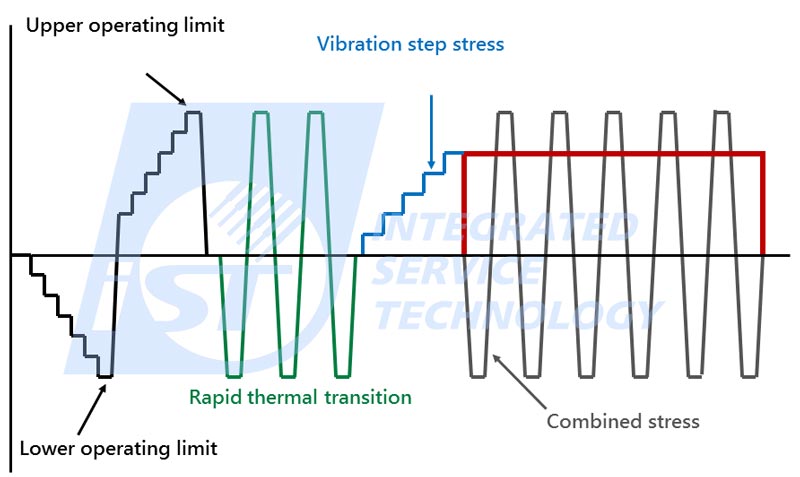
Figure 4. HALT testing for automotive manufacturers
(Source: iST)Reliability test planning should therefore go beyond “perform AEC-Q testing when AEC-Q is specified” or “perform temperature cycling when BLR is required.” It should begin with two questions:
Where will the product be installed, and what stresses will it experience throughout its service life?
V. From Components to Systems: Automotive Reliability Is More Than Repeating the Same Test Five Times
For manufacturers entering the automotive market from consumer electronics, determining appropriate reliability test conditions requires more than expanding an existing test plan.
Component selection, packaging, PCB stack-up, solder alloy, SMT conditions, material combinations, and the system’s installation environment can all affect the final reliability outcome. If reliability is considered only after the complete product has been built, correcting a failure will typically be more costly.
Automotive electronics reliability validation should therefore be planned from the product design stage, based on the mission profile and customer requirements.
As validation progresses from components to PCBs, board-level interconnects, PCBAs, and complete systems, each level addresses a new question:
- Are the components themselves reliable?
- Will the PCB remain reliable over long-term use?
- Are the components and interconnects reliable after soldering?
- Has the assembly process introduced new risks?
- Will the complete system remain reliable in its actual in-vehicle environment?
Evaluating the full path from components to systems and developing test plans around the product’s actual operating environment helps identify potential failure mechanisms earlier and establish a more comprehensive automotive electronics reliability validation strategy.
The ultimate objective is to determine whether the product remains reliable throughout its expected in-vehicle environment and service life as it progresses from individual components to a complete system.
Frequently Asked Questions About Automotive Electronics Reliability Validation
Q1. What levels are included in automotive electronics reliability validation?
Automotive electronics reliability can be validated across five levels: Component, PCB, Board, PCBA, and System.
Starting with AEC-Q component reliability qualification, validation progressively assesses the PCB, solder joints and interconnects, assembly processes, and complete ECU or electronic module under actual in-vehicle conditions. Together, these levels establish a comprehensive validation framework from components to systems.
Q2. Is AEC-Q100 qualification required for every automotive IC?
AEC-Q100 primarily defines reliability qualification requirements for automotive integrated circuits.
Its applicability and the required tests should be confirmed according to the product type, installation location, customer requirements, and mission profile.
Q3. What are the differences between AEC-Q100, Q101, Q104, and Q200?
The main difference is the type of component covered:
- AEC-Q100 applies to ICs.
- AEC-Q101 applies to discrete semiconductors.
- AEC-Q104 primarily applies to multi-chip modules (MCMs).
- AEC-Q200 applies to passive components.
Q4. How is AEC-Q007 related to BLR?
AEC-Q007 is an automotive board level reliability specification released by AEC in 2024. It incorporates electronic components, PCBs, and daisy-chain designs into BLR evaluation to assess solder joint reliability after components are mounted on a PCB.
Most AEC-Q specifications primarily focus on component-level reliability. BLR extends the evaluation to solder joints after board mounting. The release of AEC-Q007 provides a more clearly defined AEC framework for automotive board level reliability qualification.
Figure 4. HALT testing for automotive manufacturers
(Source: iST)Reliability test planning should therefore go beyond “perform AEC-Q testing when AEC-Q is specified” or “perform temperature cycling when BLR is required.” It should begin with two questions:
Where will the product be installed, and what stresses will it experience throughout its service life?
Q5. Which standards can be used to validate automotive PCB reliability?
Depending on the product application and customer requirements, automotive PCB reliability can be evaluated with reference to IPC-6012 and other relevant standards.
Evaluation may include high- and low-temperature exposure, moisture, CAF, SIR, and other factors that could affect the PCB’s long-term reliability.
Q6. Why is BLR testing still needed after passing AEC-Q qualification?
Passing component-level AEC-Q qualification primarily establishes the reliability of the component itself. It does not guarantee the same reliability after the component is soldered onto a PCB.
Differences in CTE between the package, PCB, and solder, along with solder joint design, materials, and assembly processes, can introduce new reliability risks.
BLR evaluates solder joint and interconnect reliability after board mounting, addressing risks that component-level qualification cannot cover.
Q7. Can consumer electronics reliability test conditions be applied directly to automotive electronics?
Directly applying these conditions is not recommended.
Automotive electronics differ from consumer electronics in their temperature, humidity, vibration, and mechanical stress exposure, as well as their mission profiles, expected service lives, and failure risks.
Test plans should therefore be developed around the actual installation location, operating environment, and customer requirements. Where necessary, combined environmental testing, such as temperature and vibration testing, can better represent the conditions the product may experience in a vehicle.
Q8. What does ISO 16750 primarily evaluate?
ISO 16750 addresses electrical and electronic equipment in road vehicles and evaluates its ability to withstand in-vehicle environmental stresses.
Its scope includes electrical loads, mechanical loads, climatic conditions, and chemical loads. The actual test items and conditions must be selected according to the installation location, mission profile, and OEM / Tier 1 customer requirements.
Q10. What should be done if a product fails automotive electronics reliability testing?
Failure analysis should be performed to identify the root cause and failure mode.
Corrective actions can then be implemented in the materials, structure, process, or design, followed by further validation to confirm their effectiveness.
Q9. Does passing AEC-Q qualification guarantee entry into an OEM / Tier 1 supply chain?
Not necessarily.
AEC-Q provides an important foundation for component reliability. However, OEMs and Tier 1 suppliers may also require BLR testing, system reliability validation, quality management, functional safety, automotive cybersecurity, and other customer-specific requirements.
For automotive electronics validation inquiries, please contact Ms. Chen at +886-3-579-9909, ext. 1065, or email marketing_tw@istgroup.com. We will connect you with the professional team best suited to your needs.