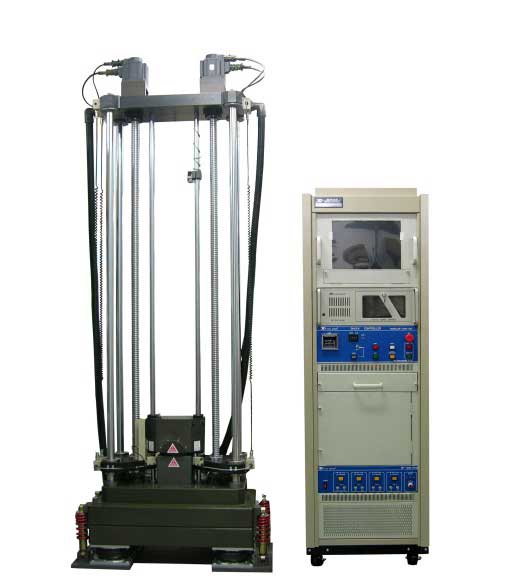
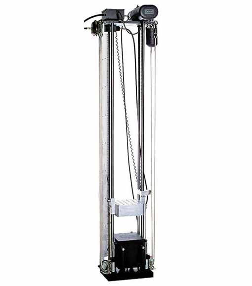
The mechanical shock test is aimed at identifying whether solder joints of ICs assembled on PCB would break when the latter is subjected to dynamic and heavy bending during process, packing, shipping, and daily use. Advanced processing capacity is shrinking product size which puts solder joints under increasingly harsh environments. The IC design industry is now setting this test as mandatory for reliability.
| Service Condition | Acceleration Peak | Pulse duration | Velocity Change | Equivalent Drop height | ||
|---|---|---|---|---|---|---|
| H | 2900 g | 0.3 ms | 543 cm/s | 214 in/s | 150 cm | 59 inches |
| G | 2000 g | 0.4 ms | 499 cm/s | 197 in/s | 127 cm | 50 inches |
| B | 1500 g | 0.5 ms | 468 cm/s | 184 in/s | 112 cm | 44 inches |
| F | 900 g | 0.7 ms | 393 cm/s | 155 in/s | 78.9 cm | 31 inches |
| A | 500 g | 1 ms | 312 cm/s | 123 in/s | 49.7 cm | 20 inches |
| E | 340 g | 1.2 ms | 255 cm/s | 100 in/s | 33.1 cm | 13 inches |
| D | 200 g | 1.5 ms | 187 cm/s | 73.7 in/s | 17.9 cm | 7 inches |
| C | 100 g | 2 ms | 125 cm/s | 49.2 in/s | 7.9 cm | 3 inches |
Failure Mode
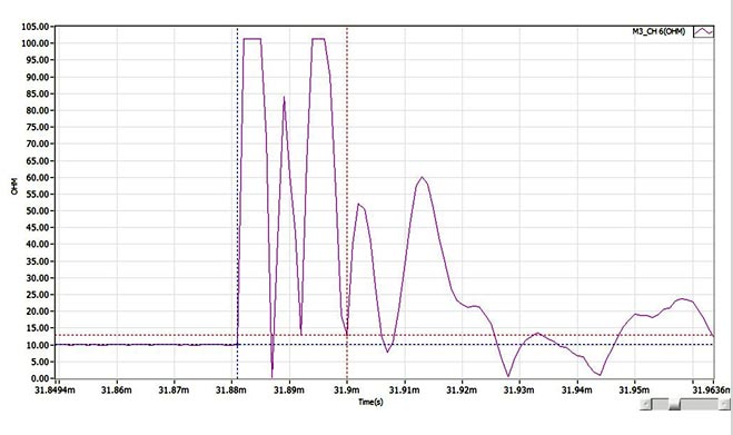
The mechanical shock test is aimed at verifying shock resistance of product and solder joints' resistance against external stress at the moment of shock. It monitors product status during the test and counts solder broken locations and areas with dye and pry or cross-section analysis afterwards.
Reference Specification
- JESD 22-B110
- JESD 22-B111
Other services you may be interested in
請輸入文字


