Issued Date: 2018/3/1
Issued By: iST
You have learnt that AEC-Q and ISO16750 certification is a must to wedge in the car electronic supply chain, but how much you know about board level reliability (BLR)?
Did you know that temperature/humidity combined vibration is one of the most critical items in proprietary BLR test specification by individual Tier 1 automotive manufacturers?
These are challenges faced by each and every company aiming to enter into car electronic markets from consumer electronic markets. The automotive industry is well known for its closed environment and reluctance in switching suppliers. Rising smart car ADAS application is changing this and offers consumer electronic makers a good opportunity. The challenge: components can be adopted in cars only when certified by a series of strict reliability tests designed to ensure product quality and protect rider safety.
Smartphone or handheld/wearable electronic devices have been establishing board level relevant tests since 2000 to ensure product service life by monitoring solder point status of IC/components mounted. Most consumer electronics makers must have well learnt about BLR for long time.
These growing test requirements in handheld electronics are recently adopted by Tier 1 car electronics module makers. A couple of them, BOSCH, Continental, and TRW, to name a few, have been setting up proprietary BLR test specifications.
The car BLR tests cover temperature cycle, thermal shock, mechanical stress, and solder point strength (including push, pull, and bend) with temperature/humidity combined vibration (THCV) being the most critical one. The latter is aimed at testing reliability of onboard electronic components subject to the simulated possible temperature environment of riding vehicles.
The iST Tech Classroom this month shall explore this reliability test focused by most leading Tier 1 car makers: Automotive BLR verification test and the most critical item in it – THCV.
Vibration tests are executed in two modes:
- Sinusoidal: Execute test in fixed frequency range at given scanning speed, time, and vibration value. This may be similar to cruising in oceans and enjoying rhythm-like ups and downs.
- Random: Execute test with different vibration in given range of frequency which is more like riding roller coasters in amusement park.
These two combined with [temperature] and [humidity] test is the so called combined vibration.
Do BLR test conditions of consumer electronics remain applicable?
No, these conditions no longer apply as the operation environment and structure of car borne platform differs. Chips employed in-vehicle are constantly subject to vibration, mechanic stress and poor external conditions especially when cars are running. A product’s qualified consumer electronics requirements may fail early in practical operation environment.
Take the vibration test; handheld products are most likely subject to simulated ordinary land, sea, and air shipment conditions while the vehicle ones shall pay more attention to temperature and humidity durability and resistance against temperature and vibration due to long time exposure to external environment. To better mimic the real operation environment the factor of vibration is added in the test environment. That is, the combined vibration test known to us.
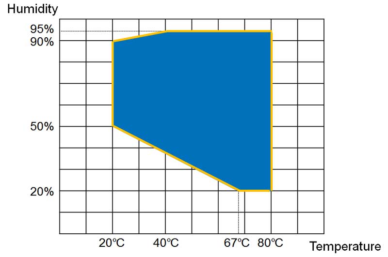
Range of temperature and humidity of combined vibration equipment
Environment at Frigid Zone and Tropical Zone differs; temperature of confined space under direct sunlight may hit 100°C or even 150°C measured close to engine. The test temperature may soar to +150°C or freeze to -40°C while humidity may vary with temperature in the blue colored area shown in the figure on the right-hand side:
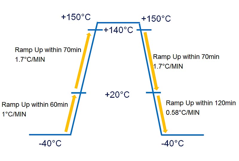
Speed of temperature change in temperature box (degree/minute)
The temperature of combined vibration equipment is completed in ways other than those adopted by ordinary temperature boxes: it is an average of the entire session rather than linear. The capacity of equipment offered by iST featuring close to 2°C temperature up and 1°C down per minute on session averages as shown in the figure below.
Items and goals of BLR test
The BLR test is designed to ensure fail-proof solder joints during operation as broken joints top the ranking cause of failure. The test process employs a daisy chain design to monitor the instant yield of samples and pinpoint failure time to help customers in identifying product weaknesses and make early improvements. Applying the BLR test in car chips is required to assess the practical operation environment with conditions covering vibration and ambient temperature. The main test items of car BLR may contain combined vibration, temperature cycle, thermal shock, mechanical stress, solder point strength (including push, pull, and bend), etc.
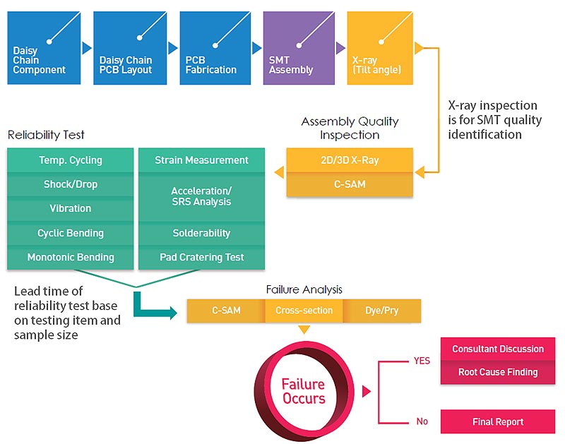
Entire process of car BLR test
The test process employed by iST may look like this:
- Run full series of reliability verification over pre-production operation from PCB design, making, and SMT mounting once samples received at iST.
- Addressing any product failure, quickly identify failure interface via board level integrated failure analysis as shown in the figure below.
- Assist customers in pinpointing causes and modify the product for another verification round and launch to the market as scheduled.
This article is aimed to share our detection and verification experiences with honorable clients like you. Should there be any sample abnormalities requiring determination or inspection, or you need to know more about the aforementioned techniques, just call Mr. Daniel Chuang at +886-3-579-9909 Ext. 6406 or email him at web_BLR@istgroup.com.