Issued Date: 2016/8/18
Issued By: iST
A smart device screen fails to turn: is it a device failure or a component defect?
If it’s a MEMS component defect: is it a leak, obstruction, or off-set? Most importantly, how do you pinpoint the cause?
As a smartphone developer or MEMS components designer, you may have encountered all or some of these grueling problems. Let us share what we have learnt in pinpointing their causes.
Case 1: Packaged MEMS encounters high resistance along with occasional open circuits
We have learnt this is a result of poor packaging. The defect can be identified easily with a “non-destructive technique analysis” due to its larger dimension after packaging. It is recommended to find this “poor joint connection” by inspection with 3D-Xray
CT.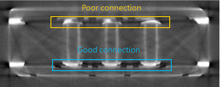
Case 2: Occasional MEMS component Q value shiftA preliminary conclusion after review with the customer suggests an error in the bonding ring of the MEMS component. An SAT
scan confirmed the bonding ring delamination result in this unstable Q value error.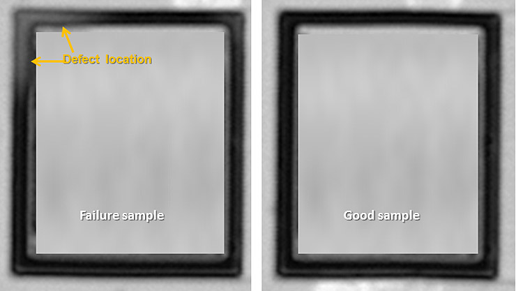
Case 3: Smartphone screen failed to rotate
We are told by smartphone manufacturers that the device is down. Further investigation found that the screen failed to rotate rather than a device failure. Our first guess indicates that the MEMS component is to blame. After its the location on the mainboard is determined, the following inspection steps are taken:
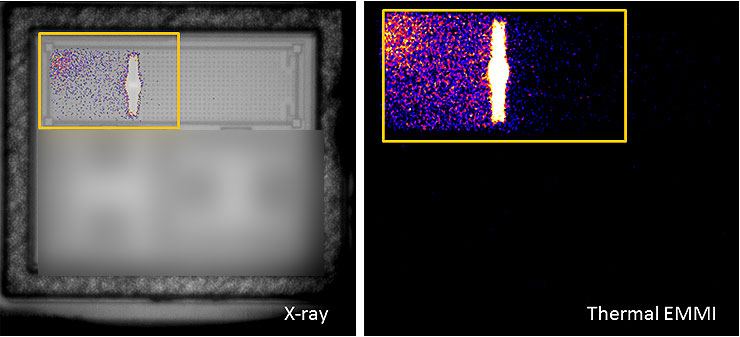
- Non-destructive Analysis: The X-ray inspection found that the MEMS component has suffered a temporary lock defect.
- Electrical experimental analysis: Thermal EMMI
inspection technique is employed to pinpoint the lock position (see figure to the right).
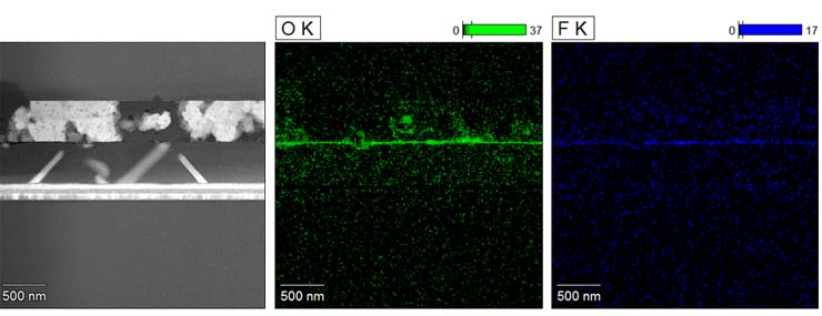
Case 4: need to observe the status of stiction film in the MEMS component
Case 5: the most vulnerable and damage prone MEMS component structure point?
We pinpointed the damage prone position of the component in the axial direction with iST’s one-stop verification and analysis platform by OM
and IROM inspection against an extracted Die.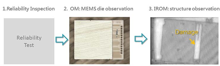
These are frequently encountered MEMS failure analysis cases. For other MEMS component failures puzzling you, please call Mr.Lee (WenJie) at +886-3-579-9909 Ext. 6612 or email her at web_ise@istgroup.com.