Issued Date:2025/4/22Automotive Power Devices
Issued By:iST
With the rapid advancement of electric vehicle, 800V power systems are becoming mainstream, and some major manufacturers have even introduced 1200V GaN (Gallium Nitride) power chip specifications. As voltage and power levels increase, so do the challenges in product reliability. How can we meet the increasingly stringent verification standards? How should we navigate the complex international regulations? Is there a comprehensive verification solution tailored for high-voltage, high-power products?
Automotive Power Devices
Recent market trends indicate that internal combustion engine (ICE) vehicles, battery electric vehicles (BEVs), and hybrid electric vehicles (HEVs) will coexist in the future, challenging the previous notion that BEVs would entirely replace traditional fuel-powered cars. On the technological front, electric vehicles are evolving toward higher voltage and power levels, with power systems transitioning from 400V to 800V becoming increasingly common. Some major manufacturers have even introduced 1200V GaN (Gallium Nitride) power chip specifications. This technological advancement helps reduce current, lighten vehicle weight, and ultimately extend the driving range of electric vehicles.
Against this industry backdrop, wide bandgap (WBG) semiconductors have emerged as a key technology, standing out with their exceptional high-voltage tolerance, thermal stability, low power loss, and high-power capabilities. These advantages have led to their widespread adoption in automotive electronics and battery energy systems, particularly in enhancing charging speed and capacity. WBG semiconductors not only accelerate advancements in power device technology but also align with the global push for energy efficiency and carbon reduction.
While the Direct current (DC) fast charging capabilities of wide bandgap (WBG) power devices present new opportunities, they also impose higher technical requirements for thermal management and reliability testing. Notably, the number of power devices used in electric vehicles is 7 to 10 times that of traditional internal combustion engine (ICE) vehicles. As a result, factors such as component performance, reliability demands, and driving safety standards make reliability verification and failure analysis critical focal points.
Addressing the increasingly stringent and rapidly evolving test regulations—and even ensuring product quality ahead of regulatory updates—has become a key concern for major global automakers. It is also a crucial investment focus for companies looking to enter the automotive electronics supply chain.
This iST Classroom will leverage iST’s 30 years of extensive hands-on experience to summarize the two core challenges that customers most frequently encounter during the R&D process:
1. How to Comply with International Standards?
With numerous international automotive regulations, which standards should be referenced for power device testing? As technology rapidly evolves, what are the latest developments in these standards that warrant attention?
2. Solutions for High-Voltage and High-Power Product Verification
As semiconductor chips advance toward higher voltage and power levels, traditional testing equipment often fails to meet the requirements. Keeping pace with customers’ R&D progress, upgrading test equipment and verification technologies has become an inevitable trend.
This edition of iST Classroom will focus on two key aspects: international regulations and verification equipment technology. We will share how to address potential issues early in the product development process to enhance market competitiveness and stand out in a competitive market.
Automotive Power Devices
Automotive Power Devices
1. What Are the Three Most Common International Standards for Power Devices?
One of the most frequent challenges faced by iST’s customers is determining which standards a product should comply with to ensure approval from downstream customers. With numerous international standards—including both public regulations and customer-specific requirements —navigating these complexities can be daunting.
This challenge isn’t unique to power devices; it applies across different semiconductor components and modules at various stages of product development. In this iST Classroom, we will focus on the three most commonly used international standards for power devices. If you have questions about regulations for other chips or modules, feel free to reach out to us.
(Read more: Reliability Test of Automotive IC (AEC-Q)、Enter the Supply Chain of EV in Five Steps: An analysis of International Automotive Reliability Specs).
The most commonly used international standards for power devices include AEC-Q101, AQG 324, and ISO 16750. As technology continues to evolve, these standards are continuously updated to keep pace with industry advancements.
Future revisions will expand or modify specifications to better accommodate the unique characteristics of wide bandgap (WBG) semiconductors. In some cases, entirely new independent documents may be introduced to address emerging market demands.
Below, we provide an overview of these three widely referenced automotive power device standards:
(1) AEC-Q101:
AEC-Q101 is one of the automotive verification standards established by the Automotive Electronics Council (Read more: the AEC-Q series standards). It focuses on stress test qualifications for discrete semiconductor devices.
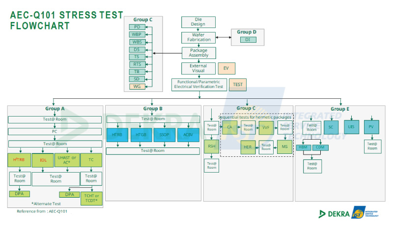
Figure 1: Stress testing process flow in AEC-Q101 (Source: DEKRA iST)
At the 2024 AEC Members Workshop held in Detroit, USA, the agenda highlighted that the usage of wide bandgap (WBG) semiconductors differs from SiC (Silicon Carbide), requiring different stress conditions. However, the current AEC-Q101 testing requirements do not fully cover WBG semiconductors. As a result, AEC plans to expand and revise the Q101 standard or establish a new independent document.
During the workshop, seven key revision points for WBG semiconductor verification were discussed: HV H3TRB, IOL, PCT, TC, GSS, BDOL, and HAST/H3TRB, as outlined below:
- HV H3TRB (High Voltage High Humidity High Temperature Reverse Bias):
In 2024, AEC officially defined the content of HV H3TRB and removed the previous 100V voltage limit in AEC-Q101 testing. This change allows laboratories to conduct tests at higher voltages under high-temperature and high-humidity conditions. - IOL (Intermittent Operating Life):
Specifically defined by AEC for bare die. It utilizes the self-heating of components to cycle between high and low temperatures, simulating long-term on/off switching operations (limited to 1,000 hours).
The air-cooled system used in IOL testing ensures a temperature difference (△Tj) greater than 100°C at the junction. As WBG power devices continue to increase in power, IOL testing has become particularly critical. - PCT (Power Cycling Test):
PCT is designed for high-power module testing, with setups that allow for real-time monitoring. At DEKRA iST, PCTs of up to 800A are currently achievable. The system uses water cooling for temperature control, continuously monitoring △Tj, TJmax, and Von/Ron to assess component behavior.
By analyzing the thermal structure function, PCT enables non-destructive detection of potential thermal resistance anomalies in the product. - TC (Temperature Cycling):
TC testing is another qualification defined by AEC for bare die. Before conducting TC testing, it is necessary to confirm the packaging method with the bare die supplier to ensure compliance with testing requirements. - GSS (Gate Switching Stress):
Current static stress tests may not adequately reflect the typical SiC MOSFET application conditions. Therefore, AEC has proposed a high-temperature gate switching stress test, which better simulates voltage drift under AC switching conditions, making it more representative of real-world applications. - BDOL (Body Diode Operating Life):
BDOL is a test for early-life failures, as most failures occur within the first 100 hours.
To screen for early failures, ELFR (Early Life Failure Rate) testing can be used. BDOL testing requires output currents of 20A or higher, making air cooling insufficient for temperature control. Instead, water-cooled plate systems can be used to maintain stable operating temperatures during testing. - HAST/H3TRB (Highly Accelerated Stress Test / High Humidity High Temperature Reverse Bias):
High-voltage testing under high-temperature and high-humidity conditions presents an arc risk. Thus, H3TRB is recommended over HAST for high-voltage testing. Testing can still be performed with mutual agreement between the user and supplier.
AEC requires all tested components to achieve zero defect results, as this is a fundamental requirement for ensuring passenger safety in automotive applications. As a result, most automakers mandate that automotive discrete semiconductor components must pass AEC-Q101 qualification.
However, since AEC-Q101 serves as the baseline requirement, real-world applications may still encounter unexpected challenges. To address this, AEC is further refining specific test conditions and requirements, such as HTGB (High-Temperature Gate Bias) and HTRB (High-Temperature Reverse Bias) testing.
By incorporating real-time monitoring of leakage currents during these tests, manufacturers can gain deeper insights into potential issues throughout the testing process, leading to more efficient development cycles and enhanced product reliability.
In 2022, iST achieved AEC recognition as Asia’s first accredited third-party laboratory after successfully passing rigorous evaluations. Going forward, iST will actively share exclusive insights from the annual AEC Members Workshop, ensuring industry stakeholders stay updated with the latest AEC standards and developments as soon as possible.
(2) AQG 324:
Unlike the AEC standards set by the U.S.-based AEC association, the AQG guidelines are established by the European Center for Power Electronics (ECPE) in collaboration with over 30 industry representatives from across the automotive supply chain.
The current AQG 324 version was released on April 12, 2018, primarily focusing on silicon (Si)-based power modules. However, future revisions will include wide bandgap (WBG) semiconductors, such as SiC (Silicon Carbide) and GaN (Gallium Nitride).
AQG 324 serves as the qualification standard for power modules used in power electronic converter units within vehicles. Since this standard closely aligns with real-world application conditions, most electric vehicle (EV) manufacturers now prioritize AQG 324 compliance when evaluating power modules.
In other words, automakers have effectively adopted AQG 324 as a standard industry benchmark.
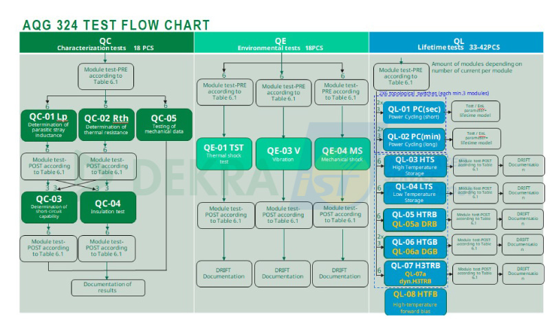
Figure 2: Testing procedure as specified in AQG 324 (Source: DEKRA iST)
For automotive power modules, AQG 324 defines two SiC dynamic reliability test methods:
- Dynamic Reverse Bias (DRB):
Similar to H3TRB (High Temperature High Humidity Reverse Bias), DRB applies dynamic bias under humid environmental conditions, validating the device at a switching frequency above 25 kHz. - Dynamic Gate Stress (DGS):
This test applies voltage variations to stress the gate, causing Vth (threshold voltage) and RDS(on) drift in wide bandgap (WBG) semiconductors. It is used to evaluate the efficiency loss of the module over time.
(3) ISO 16750:
ISO 16750 is a standard that defines environmental conditions and testing for road vehicles, covering the durability of electronic equipment in real-world automotive applications. It includes tests for temperature, humidity, vibration, and electrical loads to ensure that electrical and electronic components can withstand the conditions they encounter during vehicle operation.
This standard serves as a guideline for evaluating the environmental resilience of road vehicles, electrical systems, and electronic peripherals. The full title of the standard is: “Road Vehicles – Environmental Conditions and Electrical Testing for Electrical and Electronic Equipment.”
To address the trends and challenges associated with applying wide bandgap (WBG) semiconductors in electric vehicle products, the international standard ISO 16750 has undergone multiple revisions. In the July 2023 update, in response to the product characteristics of electric vehicle DC/DC converters, the electrical testing section now increases the voltage frequency from the original 20 kHz, specified for ICE vehicles, to 200 kHz. Additionally, the voltage range has been raised to 48V and Class B (60V~1500V), and a water-cooled thermal management system has been defined to meet the high-speed requirement of a 10 μs transient interruption test.
Additionally, the standard now incorporates mechanical stress conditions tailored for electric and hybrid vehicles, aligning with automaker-specific temperature cycling test requirements and introducing more diverse humidity testing protocols. These enhancements aim to ensure the reliability of EV components under extreme environmental conditions. The continuous updates reflect an increasing focus on the specific needs of the electric vehicle industry.
Beyond the three major international automotive standards, the rapid advancement of high-speed computing technologies—including AI and CoWoS power modules—has intensified the need to address thermal resistance (Rth) management.
Currently, thermal resistance testing follows the JEDEC 51-1 international standard, which utilizes the electrical test method. This method consists of four key measurement steps:
- Identifying the appropriate sensing current
- Calibration (K factor)
- Power conversion and data acquisition
- Structural analysis
Through structural analysis data, the thermal resistance values of each structural layer within a component can be determined. The component is typically composed of a chip, die attach, substrate, and thermal interface materials, which are often subjected to TST, TCT, or IOL to accelerate reliability verification.
By combining thermal resistance measurements with these stress tests, internal packaging defects can be quickly identified. Furthermore, thermal resistance parameters not only help detect structural abnormalities but can also be integrated with electrical parameters to calculate the Safe Operating Area (SOA) of power devices.
These non-destructive measurement methods reduce sample loss and testing time, lower R&D costs, and shorten the development and design optimization cycle.
- HV H3TRB (High Voltage High Humidity High Temperature Reverse Bias):
2. How to Ensure the Reliability of High-Voltage, High-Power WBG Semiconductor Products?
As emerging energy technologies continue to evolve, the market applications of wide bandgap (WBG) semiconductors are expanding rapidly. With the global push for solar energy, wind power, smart energy storage, and power grids, ensuring high reliability standards for WBG semiconductor products has become a critical focus.
Here are the five key areas of concern for achieving high-reliability WBG semiconductor products:
- Vertically integrated production model from materials and chips to module assembly.
- Distinguishing international automotive standards for components and modules, ensuring reliability verification to accelerate mass production.
- Precise failure analysis of power devices/modules using both non-destructive and destructive methods.
- Advancement in module packaging technologies and accumulation of thermal management experience.
- Selection of static and dynamic measurement equipment and comparison of laboratory measurement capabilities.
In response to these challenges, professional verification analysis laboratories, with their extensive experience and advanced equipment, can provide comprehensive testing and verification solutions. They assist in the reliability validation of emerging energy and high-power components, fully meeting the verification requirements of high-power and high-voltage products, including:
- High-Power and High-Voltage Verification Capabilities
We have multiple high-temperature testing systems capable of reaching 350°C, equipped with a nitrogen supply system to effectively prevent oxidation of components in high-temperature environments. These capabilities are well-suited for testing WBG semiconductors, such as SiC (Silicon Carbide) and GaN (Gallium Nitride). - Versatile Testing Capabilities
For AEC-Q101, AQG 324, and other automotive qualification tests, iST provides flexible and comprehensive solutions, overcoming the limitations of single-equipment setups that cannot cover all test requirements. - Real-Time Parameter Monitoring and Simulation Testing
By conducting pre-simulation testing, we ensure product reliability during both the assembly and actual testing phases, effectively reducing failure risks.
In response to the global push for energy efficiency and carbon reduction, WBG semiconductor manufacturers must stay ahead of rapid technological advancements by adopting the most efficient verification methods to enhance product reliability. This will be a critical focus for future product development.
Currently, SiC 1200V products are commonly operated at 60–70% of their rated voltage. However, the industry is now advancing toward higher-voltage technologies exceeding 3000V, targeting applications in solar power, wind energy, and other high-voltage systems.
With years of expertise in reliability analysis, iST and DEKRA iST provide a one-stop solution integrating failure analysis and materials analysis. Our goal is to help customers and suppliers identify potential product risks, reduce failure rates after market launch, and navigate emerging technology challenges with confidence.
※ This article was jointly edited by iST and DEKRA iST
If you have any related needs or would like to gain further insights into these topics, please feel free to contact Ms. Chen at +886-3-579-9909 ext. 8926 or via email at Sales@istgroup.com; marketing_tw@istgroup.com. For DEKRA iST, please contact sos@dekra-ist.com