Issued Date:2026/06/09 CPO GR468
Issued By:iST
The inaugural year for the mass production of silicon photonics chips is finally upon us, yet the industry still lacks a universally dedicated standard. Currently, the most authoritative baseline remains Telcordia GR-468—a classic specification introduced over two decades ago. In the face of rapidly evolving silicon photonics and Co-Packaged Optics (CPO) technologies, can this “legacy standard” still shoulder the critical responsibility of reliability verification? Furthermore, how can R&D engineers bridge the standard gap to ensure products successfully pass the bring-up phase and transition into smooth mass production?
CPO GR468
CPO GR468
TSMC explicitly pointed out at its 2026 Technology Symposium that as process nodes enter the 2nm Nanosheet era, the continuity of AI computing power must rely on a “three-layer chip cake theory” encompassing computing, heterogeneous integration, 3D IC, and—most crucially—”Photonics.” As a TSMC executive aptly stated: “When it comes to computing power, electrons are unmatched; but when it comes to signal transmission, photons reign supreme.”
In future data centers, transmission will inevitably shift from electrical to optical paths. TSMC’s advanced silicon photonics packaging platform, COUPE (Compact Universal Photonic Engine), has already been integrated onto substrates, with mass production slated for this year. Industry giants such as NVIDIA, Intel, and Broadcom are also racing into the CPO (Co-Packaged Optics) track. However, as optoelectronic components transition from “standalone modules” to “highly integrated” chip packages, the complexity of reliability verification has escalated dramatically.
When engineers ask the perennial question, “Where is the specification?”, the reality is that the industry currently lacks a single, fully dedicated standard for CPO or silicon photonics products. The most authoritative reference remains the classic Telcordia GR-468. Yet, under the trend of high-density integration, this traditional verification framework is facing unprecedented challenges.
Previously, we explored the components of silicon photonics and the keys to performance (Read more: Optical” Breakthrough: Silicon Photonics Chips Ready to Launch), subsequently sharing corresponding solutions (Read more: Why Silicon Photonics Development So Hard?Verification is the Key) and how to overcome core hurdles in mass production (Read more: Silicon Photonics CPO Nears Mass-Production Breakthrough?). We have also detailed the common failure modes of the five key components in Photonic Integrated Circuits (PICs)(Read more: Safeguarding High-Value ASICs: Why KGD Verification is the Strategic Key to Unlocking CPO Commercialization).
In this session of iST Classroom, we will look through the lens of the optical communication specification Telcordia GR-468 to share how to trace back from end-system applications to modules, components, and process levels, ensuring smooth system bring-up and mass production deployment for silicon photonics systems.
I. What Exactly Is Telcordia GR-468? Is It Still Fit for Purpose?
The telecom-grade Telcordia GR-468 is a core specification (GR-468-CORE) released in 2004 by the telecommunications authority Telcordia Technologies (formerly Bellcore). Despite its long tenure, its rigorous testing architecture remains the most widely adopted reliability verification baseline by system customers when global silicon photonics components enter the AI server supply chain.
The core value of the Telcordia GR-468 specification lies in its cross-disciplinary coverage:
1. Comprehensive Optoelectronic Chain Coverage:
It encompasses critical optoelectronic components, including Laser Diodes (LD), Photodiodes (PD), Electro-Absorption Modulators (EA Modulators), and LEDs.
2. Extensible Packaging Levels:
GR-468 categorizes the Device Under Test (DUT) into multiple Assembly Levels based on the degree of assembly completeness. The evaluation can span from wafers and bare dies to sub-modules and fully integrated optical modules, mapping distinct test conditions and verification depths to each level.
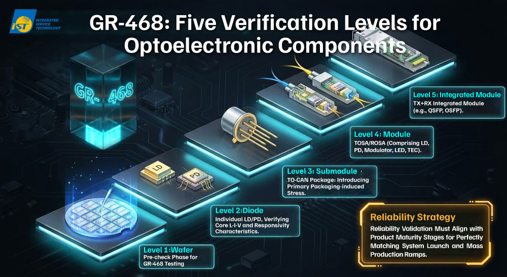
Figure 1: Schematic diagram of the GR-468 specification, illustrating a five-step verification ladder covering the complete lifecycle from wafer to the final integrated module.
(Source: iST, created with AI assistance)3. Environmental Simulation:
The GR-468 standard strictly distinguishes between Central Office (CO) environments with controlled temperatures and Uncontrolled Environments (UNC) outdoors. Different environments correspond to specific temperature ranges and stress conditions, aligning verification parameters with real-world system scenarios. This boundary is precisely where system vendors focus most, and it represents a risk source frequently underestimated in early stages.
For instance, equipment deployed in data center central offices operates under long-term controlled temperatures with minimal temperature and humidity fluctuations; hence, the stress conditions are relatively mild, and verification focuses on long-term operational stability. Conversely, as AI applications expand outward (such as Elon Musk’s vision of deploying AI computing centers into outer space), equipment placed in Uncontrolled Environments (UNC) will endure severe temperature fluctuations, damp heat, and high ambient stress. These extreme temperature differentials severely test the stability of packaging materials and optical alignment.
4. Equal Emphasis on Qualitative and Quantitative Metrics:
Beyond employing “Qualitative Tests” to determine compliance (Pass/Fail) for mass production readiness, Telcordia GR-468 leverages “Quantitative Tests / Aging Tests” for End-of-Life (EOL) estimations, reliability modeling, and system design optimization.
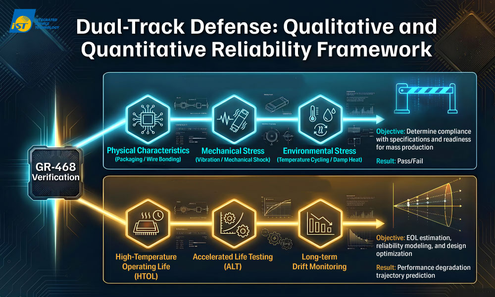
Figure 2: GR-468 balances qualitative and quantitative testing, not only determining mass production viability but also projecting total system lifetime.
(Source: iST, created with AI assistance)These structural designs of Telcordia GR-468 allow reliability verification to unfold progressively alongside product maturity, perfectly matching the cadence of silicon photonics system bring-up and mass production introduction.
II. Why Does Your System Still Fail Even After Your Silicon Photonics Components Pass the Spec?
While GR-468 has proven its enduring relevance, why do many silicon photonics systems still fail to operate smoothly in practical applications? iST has observed that even when products pass the environmental stress tests mandated by GR-468, developers frequently encounter unexplained signal degradation during system bring-up or long-term operation.
This occurs because within a CPO architecture, the interactions among optical, electrical, thermal, and mechanical vectors are incredibly complex. Traditional “Pass/Fail” determination logic is no longer sufficient to detect deep-seated failure modes that emerge post-high-density integration. Below are the two major “pain points” confronting engineers as silicon photonics advances toward system integration:
1. Thermodynamic Contradictions and ELS (External Laser Source) Compromises:
The GPUs handling core computation are high-power heat sources whose operating temperatures easily escalate to 100°C. This presents a severe thermodynamic contradiction with the laser sources, which are highly heat-sensitive and must be kept below 70°C. Subjecting a laser source to high thermal loads exponentially increases its threshold current, induces wavelength elongation (redshift), accelerates internal crystal defect propagation, and severely shortens its operating lifetime.
To resolve this contradiction, the industry is pivoting toward External Laser Sources (ELS), treating the laser source like a hot-swappable external battery. However, this architectural shift introduces new risks:
(1)Aging under High Power:
ELS must supply extremely high optical power to multiple silicon photonic engines. When operating lasers at exceptionally high drive currents, internal lattice defects expand over time under elevated temperatures, forming “Dark Line Defects” that cause a precipitous drop in luminous efficiency.iST Recommendation: Implement High-Temperature Operating Life (HTOL) testing. Continuous powering at 85°C or higher for thousands of hours allows engineers to observe optical power degradation curves and extrapolate whether the product can sustain a system lifetime of over 10 years.
(2)Vulnerability of Interconnection Interfaces:
ELS introduces extra optical interfaces. Excessive bending of Polarization-Maintaining Fiber (PM Fiber), micro-dust contamination on connectors, or mechanical micro-cracks induced by mating cycles can cause Insertion Loss (IL) to surge, creating latent system failure points.2. Stress Mismatch in Heterogeneous Integration (CTE Mismatch):
A silicon photonics chip integrates silicon, III-V compound semiconductors, glass fibers, and metals—materials with vastly different Coefficients of Thermal Expansion (CTE). For example, the massive CTE differentials among the silicon die (2.6), the PCB substrate (15), and the UV optical epoxy (50–100) generate severe mechanical stress and pulling during thermal cycles:
(1)Sub-Micron Alignment Challenges:
Coupling a Fiber Array (FA) to a silicon photonics chip demands sub-micron alignment precision. Once thermal stress triggers warpage or mechanical displacement, it can cause failures ranging from minor optical path misalignment to catastrophic structural delamination.iST Recommendation: Utilize Temperature Cycling (TC) testing. Drastically cycling between -40°C and +85°C verifies whether the optical epoxy cracks, while strictly monitoring whether IL (Insertion Loss) exceeds thresholds, rather than merely checking if the component remains electrically conductive.
(2)Adhesive Degradation and Moisture Ingress:
High-temperature and high-humidity environments cause the UV epoxy used for structural fixation to age, swell, or undergo creep, directly leading to signal loss.iST Recommendation: Execute Temperature Humidity Bias (THB) testing (commonly known as the 85/85 test). Subjecting the device to an 85°C/85% RH environment under electrical bias for over 1,000 hours ensures the structural integrity of the adhesive under extreme conditions.
With the rapid evolution of silicon photonics and CPO architectures, reliability verification should not be treated merely as a rubber stamp to secure a qualification certificate; it must actively guarantee long-term system stability.
While current Telcordia GR-468 environmental requirements primarily divide into Central Office (CO) and Uncontrolled Environments (UNC), existing standards are becoming inadequate. This gap is highlighted by the practical field-failure data accumulated by optical communication vendors, alongside the stricter environments demanded by future AI computing (such as orbital space data centers).
Consequently, the IPEC (International Optoelectronics Committee) 2025 Reliability Implementation Agreement has integrated more stringent environmental tests—including anti-sulfur, salt spray, and dust testing—for optical modules to satisfy extreme reliability mandates. The supply chain must prepare early.
Let iST serve as your silicon photonics R&D accelerator!
Please contact iST at +886-3-5799909 Ext. 1065 (Ms. Chen) or Email: marketing_tw@istgroup.com