Issued Date:2024/08/31
Issued By:iST
The automotive sector relies on the AEC-Q100 Qualification for semiconductor component reliability and robustness for current vehicle functioning and safety. Electric and hybrid vehicle technologies have high standards, making AEC-Q100 Revision J, announced in October 2023, noteworthy. It helps fulfill rising expectations for connectivity, autonomous driving, and electric powertrains so that parts satisfy tight safety and performance criteria.
Overview of AEC-Q100 Revision
History and Evolution of AEC-Q100 Standards
EVs have grown in popularity recently. The long-term trend toward electric vehicles remains solid despite Tesla’s financial problems and major U.S. manufacturer strikes. Consumers expect smart technologies; that’s why manufacturers emphasize functional safety and reliability testing for vehicle electronic components. Recently, the Automotive Electronics Council (AEC) adopted six reliability standards, including AEC-Q100 Qualification.
The Automotive Electronics Council (AEC)’s AEC-Q100 standard qualifies automotive integrated circuits. The standard was introduced to meet reliable vehicle electronics requirements and has been updated to keep up with technology. Upgrades from Version H to Revision J include improved test protocols to match contemporary EVs’ more aggressive settings.
(Read more : A Quick Glance over AEC-Q Series)
Importance of the Latest Revision in Automotive Technology
AEC-Q100 Revision J targets advanced automotive technology, including EVs and hybrids. New stress tests that better reflect real-world settings improve AEC-Q100 Qualification. For instance, the new standard contains broadened semiconductor reliability recommendations for thermal and power cycling for EVs’ changing temperature environments. It also uses higher-level failure analysis to find early failure mechanisms. Hence, components fulfill functional safety criteria and work well for better vehicle stability and customer safety.
Detailed Analysis of AEC-Q 100's Revision J
Specific Process and Packaging Changes
AEC-Q100 Qualification’s Revision J shows the shift from 28-nanometer technologies to new standards for high-end automotive applications in semiconductor processes and packaging. Most automotive semiconductor components used 28 nanometers or above techniques. Yet, Revision J now recognizes the growing need for 14 nanometers and lower processes driven by ADAS (Advanced Driver Assistance Systems). It helps handle new vehicles’ data volumes and real-time feedback.
Consequently, these chips no longer fit QFP(Quad Flat Package) forms. Instead, BGA(Ball Grid Array) and FC-BGA (Flip-Chip Ball Grid Array) packages are necessary. For automotive microcontrollers (MCUs) and high-performance computing (HPC) devices, BGA and FC-BGA improve thermal management, pin count, and electrical properties. The computational intensity of ADAS and other high-end automotive systems requires many dies and complex interconnects, which FC-BGA packaging provides.
What is more, to completely satisfy the requirements of FC-BGA products, particular attributes related to flip-chip packaging should be taken into account when considering the inclusion of family products. It’s essential to highlight that bare die products and wafer-level chip-scale packaging (WLCSP) are outside the scope of these attribute lists.
Once the defects are resolved, the next step is to ensure that automotive electronic components can operate normally under various complex and potential failure conditions and maintain product performance within the expected service life (usually 10 to 15 years). To achieve this goal, the Mission Profile flowchart (Figure 2) and the Knowledge-Based Test Methodology (KBTM) proposed in JESD 94note can be used to determine an appropriate testing plan. Communication with end users to define a suitable Mission Profile is also recommended.
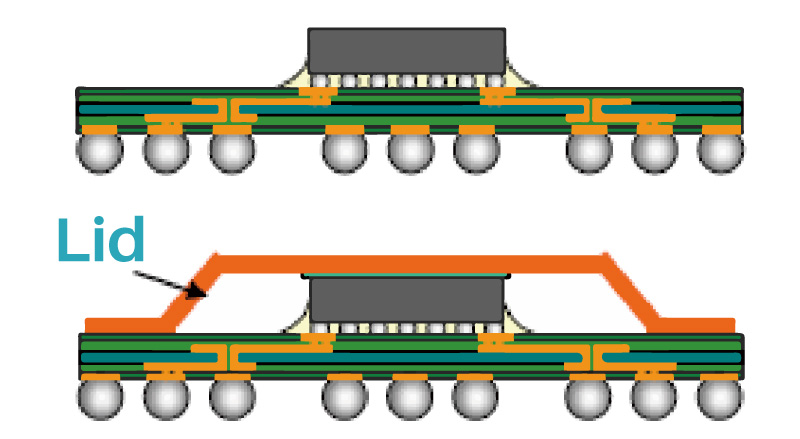
Figure 1: Representative Illustration of a Flip-Chip BGA Package.
(Source: AEC-Q100 REV. J)New Definitions and Tests Introduced
In AEC-Q100 REV-H, the guidelines did not specify processes or package forms. However, Revision J of AEC-Q100 Qualification introduces important definitions and testing protocols for ESD tolerance and FC-BGA packaging reliability. It defines exact ESD tolerances for 28-nanometer and RF components. As semiconductor components become smaller and more refined, their ESD susceptibility rises and requires strict standards for automotive reliability.
Moreover, the new FC-BGA package testing protocols simulate real-world automotive settings with thermal cycling, moisture sensitivity, and mechanical stress tests. FC-BGA packaged components in modern automotive systems must be tested for long-term reliability. The amendment emphasizes the necessity for specialized testing for varied deployment situations and automotive chip design variants to handle different environmental factors.
Additionally, in the latest revision of AEC-Q100 Qualification, there have been slight adjustments to the test content for PC (Precondition Test), THB (Temperature Humidity Bias Test), UHAST (Unbiased Highly Accelerated Stress Test), and SD (Solderability test). Nevertheless, more considerable changes in test items and conditions are as follows:
- The mandatory prerequisite for component qualification now includes whether the copper wire (Cu wire) used in automotive electronic components has obtained AEC-Q006 verification data.
- The wafer-level reliability verification item has changed NBTI (Negative Bias Temperature Instability) to BTI (Bias Temperature Instability) to encompass NBTI and PBTI (Positive Bias Temperature Instability) for current CMOS technology.
- The cycle count in Grade 0 of the Temperature Cycling Test (TCT) has been cut from 2000 to 1500, and it now requires SAT testing (Scanning Acoustic Tomography) to validate chip delamination following TCT (all temperatures).
- The Power Temperature Cycling Test (PTC) suits items with power loss ≥1 watt and power rise times <0.1 seconds, causing junction temperature (Tj) changes ≥40°C.
- For the High-Temperature Operating Life Test (HTOL), drift analysis of electrical parameters is required under applicable conditions. The FT test sequence defined as Room→Cold→Hot can be alternated with Room→Hot→Cold.
- A Bump Shear Test (BST) item has been added for FC-BGA packaging.
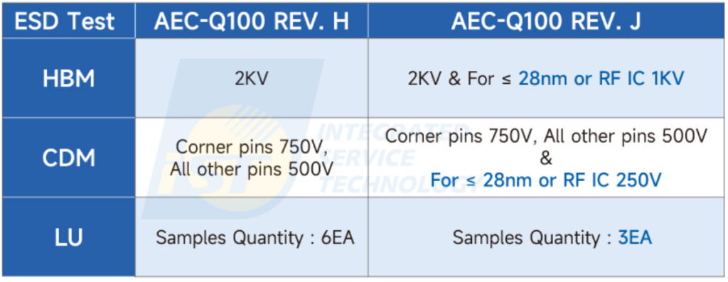
- The ESD test requirements have been changed due to the different ESD tolerances of 28-nanometer and RF chips compared to general automotive chips.
Table 1: This revision has made specific enhancements to ESD tolerance for 28-nanometer and RF chips (see blue text).

(Source: iST)
Recommendations for Failure Analysis and Mission Profile
What should be done when abnormalities or failures occur in automotive electronic components during the AEC-Q100 Qualification process? Do you need to start from scratch? It has been a persistent question for many. The Version-J specification mentions that effective failure analysis can be carried out using the 8D Report (Eight Discipline Methodology, referring to JESD 671note) and establishing appropriate improvement procedures. Such improvement measures should be validated and tracked for effectiveness and accuracy.
Once the defects are resolved, the next step is to ensure automotive electronic components can operate normally under numerous complex and potential failure conditions and maintain product performance within the expected service life (usually 10 to 15 years). To accomplish this goal, the Mission Profile flowchart and the Knowledge-Based Test Methodology (KBTM) proposed in JESD 94note can help determine an appropriate testing plan. Communication with end users to define a suitable Mission Profile is also recommended.
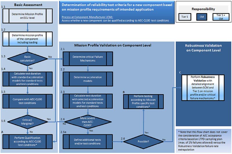
Figure 2: Flow chart of reliability test criteria for new component based on mission profile requirements of intended application.
(Source: AEC-Q100 REV. J)Impact on Automotive Chip Reliability
Enhancing Chip Reliability through New Standards
AEC-Q100 Qualification’s Revision J includes packaging and production specs that improve automotive chip reliability. It calls for expert thermal cycling testing and ESD robustness, which guarantee chips can bear strong temperature changes and electrical disturbances.
Revision J also tightens failure analysis and corrective action requirements to handle even minor deviations. The upgrade further strengthens electromigration and moisture sensitivity testing for lower long-term damage. Likewise, the new packaging requirements also include improved solder joint reliability testing to protect chip integrity under mechanical stress.
Role in Future Automotive Technologies
Future autonomous driving and electric powertrains hinge on AEC-Q100 Revision J. Autonomous automobiles need reliable chips to analyze massive real-time data. It is fixed by enhancing fault coverage and adding mixed-signal and digital IC stress testing in Revision J.
New electric powertrain standards boost isolation robustness and thermal management for lower high-voltage risks. It is important because EVs have different thermal profiles from combustion engines. Power cycling and HTOL testing are now part of the AEC-Q100 Qualification, which supports the life expectancy of EV power electronics. More rigid electromagnetic compatibility (EMC) testing addresses thermal runaway and EMI.
For further details, please contact Ms. Sherry Wu at +886-3-579-9909 ext. 6403 or email her at web_rce@istgroup.com or marketing_tw@istgroup.com.
For the complete AEC-Q100 revision document, please click this link.