Issued Date:2023/9/12 Thermal Analysis
Issued By:iST
There are countless types of advanced packaging materials, and most material characteristics are closely linked to “heat.” But just how significant is the influence of thermal characteristics on the lifetime and stability of components?
When we measure material characteristics through thermal analysis or reference material specifications provided by manufacturers, can we be certain that these values are absolutely accurate? Thermal Analysis

In the face of physical limitations and bottlenecks encountered in semiconductor technology development, Moore’s Law is gradually losing its foothold in semiconductor processes. Coupled with the escalating costs of transistor miniaturization processes, a balance between technological advancement and cost has become the pursuit. The emergence of “advanced packaging” has presented an effective solution.
The year 2023 witnesses an AI (Artificial Intelligence) frenzy sweeping across the globe, with the core of AI development lying in high-performance computing (HPC). However, advanced packaging often relies on a “three-dimensional structure” stacking method to achieve the goals of compact size and enhanced performance. Yet, the layered stacking of materials along with complex structures gives rise to factors such as heat dissipation and thermal expansion, which significantly impact product stability and lifetime.
In the previous iST classroom we have shared insights on “Exclusive Test Methods Get TIM Defects Checked Quickly” and “Count Warpage Amount Before SMT to Avoid Solder Empty and Early Failure” In this edition, let’s delve into the importance of thermal characteristics in material selection for packaging and explore the application of thermal analysis tools to measure these thermal characteristics.
Thermal Analysis
Thermal Analysis
1.Types and Significance of Packaging Materials: Why Consider Thermal Characteristics?
Prominent advanced packaging techniques available in the market include 2.5D packaging technologies like CoWoS and I-Cube, as well as 3D packaging technologies such as SoIC, InFO, XCube, Foveros and so on.
These diverse packaging formats and technologies share a common feature: they utilize encapsulation through molding processes to seal the entire component, including the chip, protecting it from external elements such as moisture, dust, electrostatic force, corrosive gases, or UV light. Typically, semiconductor packaging materials primarily involve adhesives that offer bonding, support, and protection.
The spectrum of packaging materials ranges from metals and plastics to ceramics and more, each with their own advantages and suitable applications. For instance, metal packaging boasts superior mechanical strength and heat dissipation properties, often with inherent electromagnetic shielding capabilities. Ceramic packaging materials exhibit a low dielectric coefficient, corrosion resistance, and minimal thermal expansion. Meanwhile, plastic packaging stands out for its lower cost, lightweight nature, excellent insulation, and impact resistance, making it a prevalent choice in semiconductor packaging.
Taking a comprehensive view of the various material attributes discussed above, it’s evident that many material characteristics are closely tied to “heat.” Therefore, when selecting packaging materials, it’s crucial to consider their thermal properties to ensuring that the chosen materials of the components can withstand the operating temperatures and guarantee the overall stability and lifetime of the operation.
To enhance understanding, let’s take the most common “plastic packaging materials” as an example. The composition of plastic packaging materials primarily includes phenolic resins, epoxy resins, and silicone resins. Among them, epoxy resins are widely used, often applied as Underfill (UF) materials for support and insulation, or as Molding Compounds (MC) for protective casing. Here, we’ll use a specification sheet for Underfill as an example (Figure 1) to provide a preliminary introduction to several common thermal characteristics and related tests.
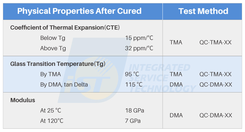
Figure 1: Example specification sheet for plastic packaging underfill material
2. Understanding the Significance of CTE and its Measurement
To establish a foundational understanding of material thermal properties, it’s essential to begin with the Coefficient of Thermal Expansion (CTE). CTE is a temperature-dependent parameter, varying with changes in temperature. In the specification sheets of plastic packaging materials, the Glass Transition Temperature (Tg) is often used as a reference point for differentiation.
For instance, in the specification sheet shown in Figure 1, the CTE values between room temperature and the Tg are quite similar to the CTE values typically observed in the horizontal direction of printed circuit boards (PCB). However, once the Tg point is surpassed, the CTE values undergo noticeable changes. within this temperature range, the possibility of product issues may arise due to CTE mismatches. These issues could include delamination or bending of PCBs, as well as the potential for component or part fractures and open circuits. Therefore, the CTE parameter information plays a vital role in material selection, serving as a significant indicator of material suitability.
How is CTE Measured? Different specifications can be referenced based on sample material and testing equipment. Figure 2, compiled by iST Materials Analysis Laboratory, illustrates common testing specifications suitable for Thermal Mechanical Analyzer (TMA). However, it’s important to note that testing values seen in specification sheets are often obtained through testing methods devised by material manufacturers. Therefore, these values are typically meant for comparative reference.
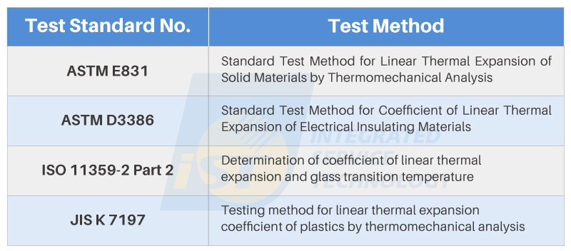
Figure 2: Common TMA testing specification
3. Why is it Necessary to Measure the Tg?
Earlier, we mentioned that CTE is a function of temperature, and mismatched CTE can lead to various adverse effects. So, why is Tg used as a boundary to observe CTE? To understand this, we need to delve into what Tg is and the characteristics of materials with Tg at different temperatures.
Similar to other phase transition points such as melting and boiling points, Tg is a “reversible transition temperature” that defines the shift between two states of a substance. While melting signifies the transition from solid to liquid, and boiling marks the shift from liquid to gas, Tg pertains to the transformation within the solid state. Unlike the more pronounced volume changes seen in the transitions between solid, liquid, and gas phases, Tg is relatively less apparent.
The relationship between a material’s physical properties and temperature can be illustrated using Figure 3. At low temperatures, materials tend to exhibit relatively hard and brittle characteristics. As the temperature rises, the non-crystalline regions of the material’s molecular chains gain energy, allowing for increased mobility. This results in the solid material adopting a more flexible, rubber-like behavior. These two distinct states are often referred to as the “glassy state” and the “rubbery state.” The temperature at which this transition occurs is termed the “glass transition temperature,” or Tg. This signifies the intermediate temperature region between the two states and serves as a pivotal point in material behavior.
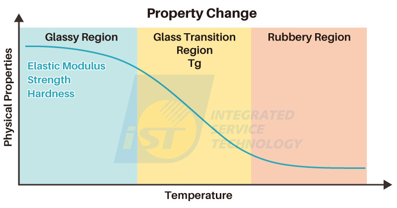
Figure 3: Relationship between physical properties and temperature
From the diagram above, it is more appropriate to consider Tg as a “temperature range” instead of a fixed temperature. To ensure reliability and a longer lifetime, users can select materials with suitable Tg values based on processing requirements and the product’s operating environment.
So why is the Tg point in specification sheets often a single temperature value rather than a range? This involves the matter of “definition.” Different testing standards define the measurement and methodology for determining the Tg point. This standardization allows for meaningful comparisons of Tg points under similar circumstances.
The methods for testing Tg can be broadly categorized into three types. Apart from the TMA and Dynamic Mechanical Analyzer (DMA)。 mentioned in Figure 1’s specification sheet, another approach involves the use of a Differential Scanning Calorimeter (DSC), which offers greater tolerance for varying sample conditions. Figure 4, compiled by iST Materials Analysis Laboratory, illustrates these three testing methods alongside common Tg point test specifications.
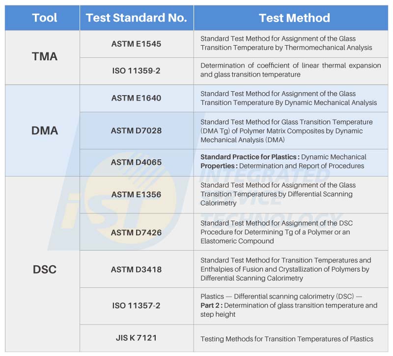
Figure 4: Testing Methods and Common Tg Point Testing Specifications
How to choosing the right tool for Tg point testing?
Insights from iST Materials Analysis Laboratory reveals that each testing equipment has specific requirements for sample conditions and dimensions. For materials suppliers or those who possess raw materials, they can create test specimens according to the equipment’s requirements. Generally, Dynamic Mechanical Analyzer (DMA) is particularly sensitive in detecting viscoelastic properties, while TMA testing is conducted by preparing specimens as needed.
DSC relies on the difference in Specific Heat Capacity (Cp) at different temperatures to measure Tg points. Thus, materials with substantial Cp variations exhibit better testing sensitivity. Nonetheless, DSC boasts its own merits: it demands minimal sample quantities, lacks size constraints, and can even measure powders with sufficient weight. This makes DSC a convenient testing tool for small quantities or powdery materials. (For further information on the comparison of thermal characteristic testing tools such as DSC, TMA, and DMA, please feel free to contact us at marketing_tw@istgroup.com)
4. Understanding Modulus and Measuring Mechanical Properties
In addition to the aforementioned CTE and Tg material properties, mechanical characteristics also play a significant role in material selection. Common mechanical attributes include stiffness and impact resistance. These two properties can be simplified as follows: softer materials are more prone to stretching and bending, and they tend to dissipate received impact energy as heat or deformation; conversely, harder materials resist external deformation, allowing them to retain and transmit greater amounts of energy.
Within specifications, “modulus” generally pertains to elastic modulus. Defined as the ratio of stress to strain, modulus shares similarities with stiffness, but the distinction lies in stiffness requiring consideration of sample structure and shape, while elastic modulus is an inherent material property, independent of structure.
Modulus is also temperature-dependent, generally decreasing with rising temperatures. This aspect allows process engineers to choose appropriate processing temperatures. Specifications typically provide modulus values at room temperature. If temperature-specific testing is needed, measurements can be conducted using DMA or tensile testing machines equipped with heating capabilities.
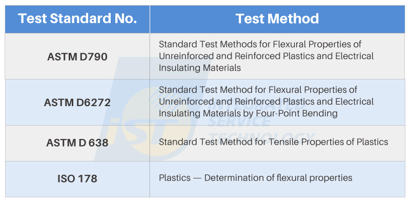
Figure 5: Common Test Standards for Elastic Modulus
Figure 5 presents several common testing methods for elastic modulus measurement. Keen readers may observe the presence of two types of testing specifications: Flexural Properties and Tensile Properties in the testing standards. The reason for this lies in the difference in “testing direction,” which is closely tied to the definition.
“Bending,” as the term suggests, involves bending the material to observe its strength characteristics. This can be done using three different methods: two-point, three-point, or four-point bending. On the other hand, “tensile” testing applies force along the material’s axial direction, involving either stretching or compression. By monitoring the dimensional changes along the sample’s axial direction, the corresponding strength can be calculated. The widely known Young’s Modulus is an example of elastic modulus determined under tensile conditions.
5. Are Thermal Analyzer Measurements Accurate?
Will measurements from newly packaged chips, chips stored for a period, or even used chips match the values in the specifications? Can the mentioned testing methods be used to verify material compliance? Are they suitable for incoming inspection tests? Can these tests be used to speculate whether failures are due to material variations or degradation?
The answers to these common inquiries can both be affirmative and negative.
First and foremost, the fundamental point is the importance of “definition,” a concept frequently emphasized throughout. The method and conditions of measurement need to be explicitly stipulated to ensure comparison is made on the same basis.
Moreover, an essential factor to consider is that all thermal analyses involve “heat.” The history of heating, cooling, and the duration experienced by a sample collectively shape its current state, termed its “thermal history.”
When conducting experiments involving heating or cooling samples to obtain relevant data, it’s essential to consider the thermal history conditions of the samples. If the samples have different thermal histories, the comparison basis becomes skewed. This is why the term “eliminating thermal history” is frequently heard in thermal analysis. This process involves subjecting the samples to appropriate heat treatment conditions, allowing them to reach a comparable testing baseline, before proceeding with the actual data collection phase of the experiment.
Nonetheless, not all data collection requires the elimination of thermal history, and such an action might even render the results incomparable. For instance, when measuring Tg points, eliminating thermal history can enhance the accuracy of material crystallization characteristics, ensuring comparable experimental outcomes. Conversely, eliminating thermal history from thermosetting resins could alter the curing state, preventing accurate assessment of the material’s current condition.
Thermal analysis is only a small part of packaging material analysis. When we unfold the entire specification sheet, it’s apparent that creating a material involves combining various physical, electrical, and chemical properties. It’s truly remarkable to admire the designers and developers who craft these materials, considering the vast amount of knowledge and skill required to provide the semiconductor industry with such diverse and sophisticated materials for application.
This is to share knowledge and experiences of iST with you. Should there be any inquiry or if you would like to know more about the aforementioned techniques, just ring Neal Chiang at +886-3-579-9909 Ext. 6176 or email him at sa_tw@istgroup.com;marketing_tw@istgroup.com。