Issued Date:2024/11/26DisplayPort
Issued By:iST
With the rapid growth of the eSports market, demand for high-performance display technologies has surged. DisplayPort (DP), known for its exceptional data transmission capacity, multi-monitor linking capabilities, and versatile peripheral expansion, has become a critical video interface in the market.
DisplayPort
The eSports industry is booming. According to Statista, Germany’s research institute, during the 2023 World Championship of League of Legends, the world’s most popular eSports game, over 6.4 million viewers tuned in—significantly surpassing the 1.56 million viewers of that year’s NBA season broadcasts. NewZoo reports that by 2025, global eSports viewership will reach approximately 64 billion, meaning nearly one in eight people worldwide will watch eSports events. Additionally, the International Olympic Committee has voted to host the first Olympic eSports Games in Saudi Arabia in 2025. This growth in audience is creating further commercial opportunities within the eSports industry and has increased the demand for high-definition, multi-channel transmission and multi-device connection display technologies.
Within this fast-developing multimedia environment, HDMI (High Definition Multimedia Interface) and DisplayPort (DP) stand as the two primary video interfaces. Since the 2000s, these technologies have evolved along different paths, each finding strength in distinct product categories.
HDMI, widely used in multimedia systems like TVs, AV receivers/amplifiers, set-top boxes, and gaming consoles, supports high-definition audio and video, including 4K and 8K resolutions, HDR, and simultaneous audio-visual transmission. HDMI is predominantly applied in consumer electronics, offering broad compatibility and high accessibility.
DisplayPort, in contrast, is distinguished by its high refresh rate and ultra-high resolution (with a theoretical max of 16K, though no products currently reach this specification). DisplayPort also enables multiple monitor connections (through MST, or Multi-Stream Transport) and is suited for high-performance, high-bandwidth applications, commonly used in PC monitors and professional workstations. In recent years, DisplayPort’s integration with USB Type-C has gained traction within the eSports industry and devices compatible with USB Type-C, as it seamlessly combines with standards like USB and Thunderbolt.
In this edition of iST’s classroom, we’ll explore the most common testing challenges that clients face with DisplayPort (DP). Through real-world examples from iST’s Signal Integrity Laboratory, we provide practical testing insights to help advance your products in the eSports market and other ultra-high-definition professional image processing industries.
DisplayPort
DisplayPort
1. What is DisplayPort?
DisplayPort (DP) is a video interface standard managed by the Video Electronics Standards Association (VESA). Developed by the display chip and monitor industries, DisplayPort is the next-generation audio-visual transmission interface that enables high display performance, stability, and versatility, enhancing user experience and device operation across a range of applications.
Since the release of DP1.0 in 2006, DisplayPort has undergone over ten revisions, with the latest being DP2.1a, introduced at the end of 2023. The most commonly used version, DP1.4 (released in 2016), increased the data rate from the 5.4 Gbps of DP1.2 to 8.1 Gbps, enabling resolutions up to 7680×4320 (8K) at 30Hz. With DP1.4’s Display Stream Compression (DSC) feature, resolutions of 7680×4320 at 60Hz can be transmitted over a single cable. This version also introduced HDR (High Dynamic Range) and Adaptive Sync, elevating the overall visual experience.
The newly launched DP2.1 represents a milestone advancement. Link rates jumped from 8.1 Gbps to a maximum of 20 Gbps, with encoding efficiency improved through support for 128b/132b alongside the traditional 8b/10b. With DSC, DP2.1 supports resolutions up to 3840×2160 (4K) at 240Hz or 10240×4320 (10K) at 60Hz, with future plans to accommodate 16K (though no products yet reach this).
Table 1: Comparison of Link Rates for DP2.1 and DP1.4. DP2.1 supports backward compatibility with DP1.4 link rates. Notable terms: UHBR, Ultra High Bit Rate; HBR, High Bit Rate, RBR: Reduced Bit Rate.
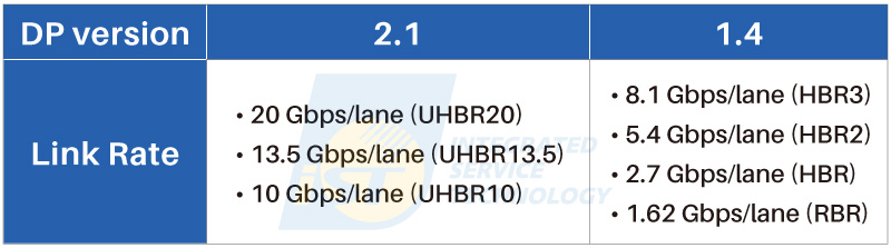
(Source: DisplayPort official website; Table created by iST)
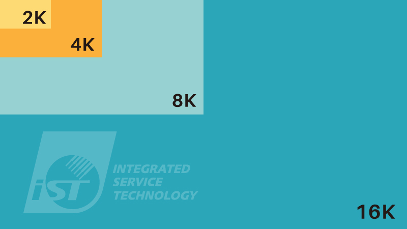
Figure 1: Comparison of Resolutions and Bandwidth. Bandwidth and resolution share a relationship similar to irrigation channels; larger fields require larger channels for effective water supply. (Source: iST)
In response to higher transmission rates, VESA introduced new cables and enhanced DP connector standards. Although some new cable specifications are currently shorter, VESA is actively working on length issues, aiming for smoother user experiences. Shorter cables could be practical for mini PC setups, such as Intel’s NUC, allowing for neater cable management behind the monitor.
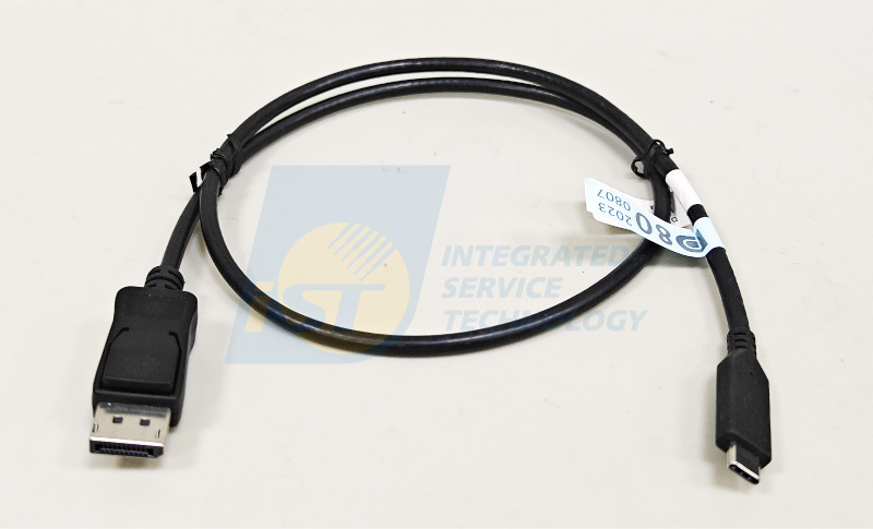
Figure 2: VESA’s New DP80 Type C to Enhanced DP Cable Supporting up to UHBR20, this short-length cable has a DP connector on one end and a Type-C connector on the other. Unlike dual Type-C cables, it solely functions for DP and does not support USB data transfer or power supply. (Source: iST)
For more DP2.1 features, refer to the VESA website.
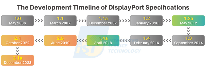
Figure 3: The Evolution of DP Standards. DP 2.X has progressed from versions 2.0 and 2.1 to the current 2.1a, as DP2.0 and DP2.1 were released some time ago, discussions now predominantly focus on the DP2.1a standard. Gray Sections: Represent transitional periods between versions; Green Sections: Indicate the standards currently used for certification; Orange Sections: Denote developing or planned standards still under refinement (Certification of DP2.1 has also started). (Source: DisplayPort official website; Image created by iST)
2. Key Features of DisplayPort: Ideal for Multi-Monitor Work
DisplayPort (DP) stands out not only for its ultra-high refresh rate and resolution, providing a smooth and seamless viewing experience, but also for the following distinctive features:
(1) Compatibility and Expandability
DP devices can seamlessly connect to traditional video interfaces like HDMI, DVI (Digital Visual Interface), and VGA (Video Graphics Array) using various adapters. Since joining the USB Type-C family, DP enables the transmission of video, data, and power via a single Type-C cable. When combined with a Type-C docking station, it offers expanded connectivity options, such as DP, HDMI, Type-C, Ethernet, USB, SD card slots, headphone jacks, and optical audio. This setup allows users to connect multiple devices and displays using a single Type-C cable with the flexibility of connecting at different locations.
(2) Enhanced Multi-Monitor Efficiency and Entertainment
DP’s Multi-Stream Transport (MST) capability is perfect for multitasking, as it allows simultaneous operation across multiple monitors. For instance, a typical workstation setup with MST and three monitors can display four to six documents simultaneously, improving productivity. With this flexibility, users can easily disconnect their laptops by removing one Type-C cable or set up monitors vertically or horizontally based on needs, making DP an excellent choice for creative work and media tasks. It’s equally convenient for entertainment setups.
Comparing HDMI and DP Multi-Monitor Connectivity (Figure 4 and 5). When using HDMI for multi-monitor setups, each monitor requires a corresponding HDMI port. However, most laptops offer limited HDMI slots, restricting scalability. In contrast, DP can daisy-chain monitors, enabling the connection of multiple external displays through one port, enhancing productivity and screen real estate.
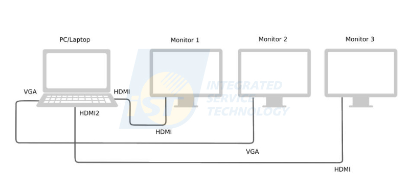
Figure 4: HDMI Multi-Monitor Setup (Source: iST)
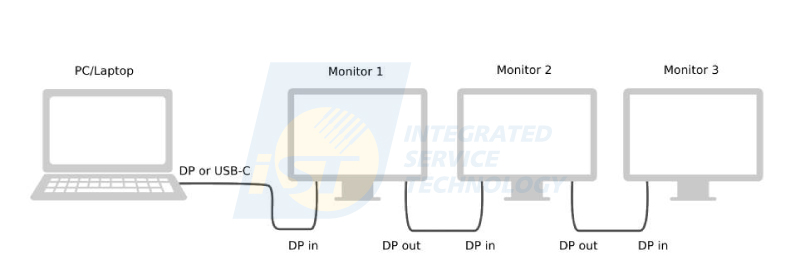
Figure 5: DP Multi-Monitor Setup (Source: iST)
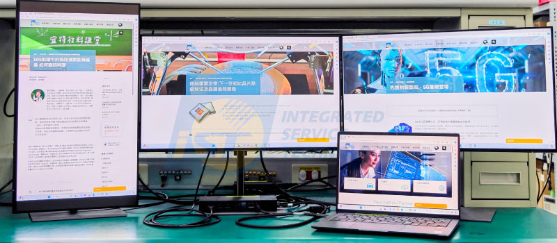
Figure 6: MST and Docking Station Setup with Multiple Monitors – An Illustration of Practical Use. This setup shows how a laptop can seamlessly connect to three monitors and multiple peripheral devices through a docking station. (Source: iST)
(3) A New Possibility: Powering Laptops via Monitors?
With recent advancements, a setup where a Type-C monitor supports DP ALT Mode and 100W USB Power Delivery (PD) enables laptops to be powered through the monitor alone. This configuration requires just one Type-C cable to supply power to the laptop, transmit the image simultaneously, and connect USB devices through the monitor’s USB hub. This level of functionality was unimaginable with previous technology.
(4) Adaptability for Advanced Applications
VR and AR devices require high bandwidth to deliver immersive, high-resolution visuals, making DP an ideal interface for these applications. Previously, these devices relied on unique or proprietary cables for connectivity. Now, with DP’s integration into Type-C, a single Type-C cable can handle data, video, and power transmission. This shift makes it easier to connect DP-capable mobile devices, such as smartphones and handheld gaming consoles, enhancing versatility in various setups.
3. iST DisplayPort (DP) Test Case Insights
At iST’s Signal Integrity Testing Lab, a structured process is applied to each DP product—from debugging and testing to certification. Each sample is treated meticulously to ensure compliance with DisplayPort standards. Testing encompasses diverse parameters like: PHY (Physical Layer) for electrical characteristics, Link (Communication Protocol) for reliable data transfer, EDID (Extended Display Identification Data) for display identification accuracy, and
IOP (Interoperability) for cross-device compatibility. The lab also provides custom testing services to meet specific client needs.Below are three frequent testing scenarios encountered:
(1) Case 1: Quickly Resolve Common Issues During the Initial Phase of Product Testing
To minimize time loss for clients, initial troubleshooting is performed based on supplier-provided chip details. Common cases include:
- Chip A: When in Power Saving Mode, it fails to report error bits. The solution involves disabling this mode through the system’s on-screen display (OSD) menu or alternative methods.
- Chip B: Testing may encounter signal unlock issues if the firmware doesn’t use a fixed port. Processing the “fixed port” in the setting menu to see if this situation improved.
- Chip C: Some tests require specific operational modes; thus, verifying the device is in the correct mode is essential.
Once these issues are resolved, further checks are done to see if the problem lies with the firmware settings or other factors. These are common early-stage issues that, with our expertise, can prevent wasted time due to engineers not fully understanding the product’s characteristics. Customers can always connect with our laboratory engineers to swiftly resolve issues.
(2) Case 2: Using Third-Party Tools for Debugging and Providing Data Analysis Support
When DP products encounter problems during testing, we can assist by using third-party tools, such as PD Sniffer or AUX Monitor (Auxiliary Monitor), to provide data for customer analysis. For issues that can be identified by iST, we also offer recommendations or guidance to help the customer troubleshoot effectively.
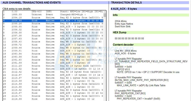
Figure 7: Using the AUX Monitor to record AUX logs and analyze issues, confirming link training status and DPCD (DisplayPort Configuration Data) states. (Source: iST)
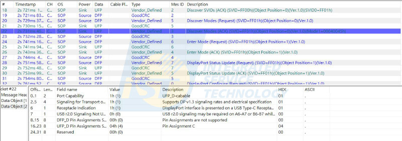
Figure 8: Using PD Sniffer to Record Logs and Analyze Issues, Confirming Whether the Test Properly Enters DP ALT Mode. (Source: iST)
(3) Case 3: Ensuring Stable DP System Operation through AUX Channel Signal Analysis and Troubleshooting
In DP testing, the AUX Channel serves as a critical communication bridge between the Source and Sink. The following case demonstrates how to use an oscilloscope to measure and analyze AUX Channel electrical signals.
In Figure 9a, the signal at the AUX end (blue) is abnormal due to improper configuration, preventing correct signal transmission. Signal analysis was performed using a single-ended probe.
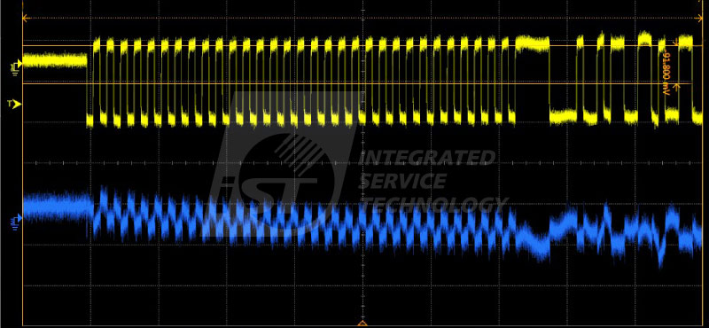
Figure 9a: Using an oscilloscope to confirm issues in the DP AUX Channel, where the signal from oscilloscope channel 3 is clearly distorted (see blue waveform).
(Source: iST)Figure 9b shows that the positive and negative terminals of the AUX Channel should have signals with opposite phases and equal amplitude (see Figure 9c). A single-ended check revealed that due to incorrect settings, both signals had the same phase, which, after differential processing, resulted in a very small amplitude and caused failure in device recognition. The normal AUX Channel signal after differential processing is shown in Figure 9d.
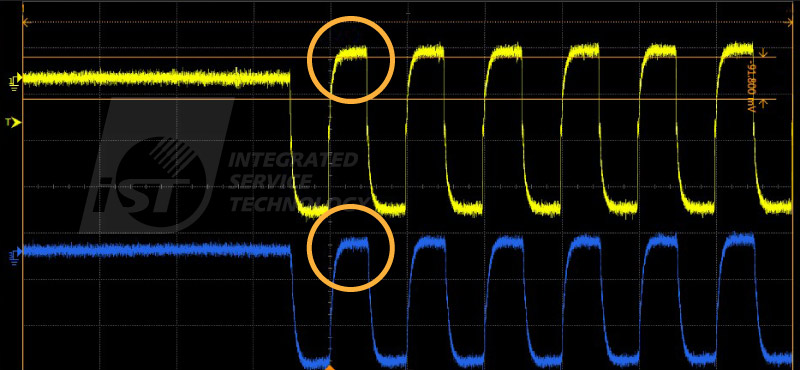
Figure 9b: Using an oscilloscope to confirm DP AUX Channel issues, where the positive and negative terminals of the AUX Channel have the same phase. (Source: iST)
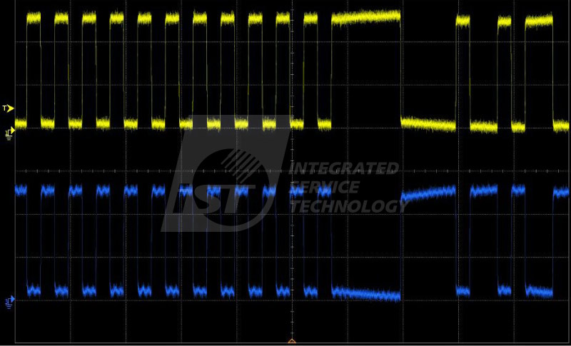
Figure 9c: This figure shows the normal waveform of an AUX Channel, where the positive and negative signals should have equal amplitude and opposite phase. (Source: iST)
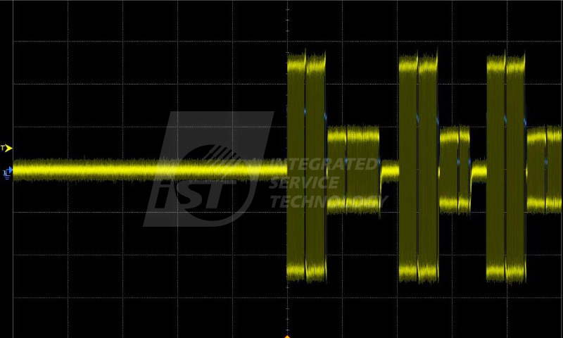
Figure 9d. The normal AUX Channel signal after differential processing.
(Source: iST)When the Source’s AUX_CH DC Level is configured incorrectly, it may prevent communication with the AUX Controller, leading to testing failure (Figure 9e).
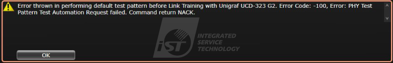
Figure 9e: A warning dialog that appears when the Source’s AUX_CH DC Level is configured incorrectly. In this case, the AUX+- voltages are both 3V, while they should be 0.3V and 3V. Using the AUX Monitor, we observed that after the Reference Sink performed the HPD action, there was no further response from TX. (Source: iST)
When the AUX Channel fails to transmit signals correctly, it can cause DP Link Training to fail, preventing full functionality. Although the AUX Channel’s transmission speed is not high, it plays a crucial role in connecting devices and exchanging messages via the AUX Channel, enabling Link Training before video and audio transmission. Figure 10 illustrates the main components of the DP channel.
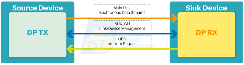
Figure 10: Main components of the DP channel: a 4-channel high-speed Main Link with signals transmitted from DP TX to DP RX, plus a pair of AUX_CH for bi-directional half-duplex communication, and an HPD (Hot Plug Detect) channel initiated by DP RX for HPD or HPD_IRQ (Interrupt Request). (Source: DisplayPort official website; Image created by iST)
If PHY measurements are interrupted, we can use an oscilloscope to confirm the waveform (Figure 11).
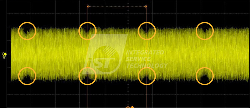
Figure 11: Interrupt during PHY measurements; using an oscilloscope to confirm the waveform, showing signal anomalies occurring at fixed intervals.
(Source: iST)
As a VESA-certified laboratory, iST continues to share the latest standards. In a rapidly evolving product landscape, beyond standard certification tests, we leverage our extensive experience to assess customer-provided block diagrams or related data, recommending appropriate test procedures. For non-standard products, iST Signal Integrity Testing Lab can discuss the desired tests with clients’ engineering team to evaluate feasibility and ensure the best assistance and results during the testing process.
For any questions regarding DisplayPort certification, feel free to contact iST Signal Testing Laboratory at +886-2-2792-2890 ext. 2738, Mr. Chris | Email: web_si@istgroup.com;marketing_tw@istgroup.com