Issued Date:2024/5/14 AEC-Q007
Issued By:iST
Previously, the Board Level Reliability (BLR) testing for ICs onboard to PCBs in automotive applications was only briefly mentioned in the AEC-Q104 standard. Much anticipated, the AEC-Q007 standard for BLR in automotive applications was finally introduced in March this year. Let’s quickly explore what AEC-Q007 entails.
AEC-Q007

AEC-Q007
AEC-Q007
The Automotive Electronics Council (AEC), the leading authority in global automotive electronics, recently announced the release of the AEC-Q007 specification, which officially defines the verification standards and guidelines that can be followed for Automotive BLR testing.
Before probing further into AEC-Q007, let’s first introduce the family members of the AEC Component Technical Committee, there are AEC-Q100 (IC Chips), AEC-Q101 (Discrete Components), AEC-Q102 (Discrete Optoelectronic Components), AEC-Q103 (MEMS, Microelectromechanical Systems), AEC-Q104 (MCM, Multi-Chip Modules), and AEC-Q200 (Passive Components).
These specifications primarily focus on conducting various tests at the component level. Although the AEC-Q104 specification mentions Board Level Reliability (BLR) in Test Group H, it only provides some reference specifications and does not provide detailed explanations regarding PCB and Daisy Chain design considerations. If you are interested in this specification, you can refer to the following article: Six Key points to Learn the AEC-Q104 for Automotive MCM in No Time
In other words, the previous AEC specifications primarily focused on component-level testing until the recent release of AEC-Q007 in March of 2024. With AEC-Q007, there is now a comprehensive integration of components and PCBs (printed circuit boards), bringing forth the popular specification for BLR verification in automotive applications.
According to the Daisy Chain design (Figure 1) mentioned in AEC-Q007, this is actually what we commonly refer to as BLR verification. The principle of BLR verification involves designing the solder joints and PCB in a conductive mode to create a loop to observe the lifespan of solder joints (Read more: PCB design: Key to pass or fail in board level reliability tests). During the testing process, measurement equipment is used to obtain real-time information for determining solder joint yield.
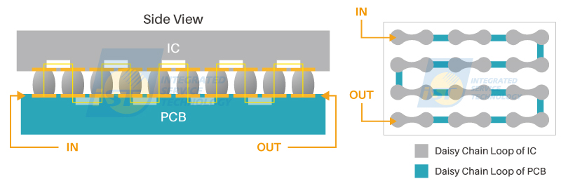
Figure 1: Overview of BLR Daisy Chain Design. (Source: iST)
In the past, AEC certifications focused solely on component-level qualifications. However, with the release of AEC-Q007, PCBs are now taken into consideration, and the BLR verification method is employed to observe solder joint failures. In addition to the testing method, the specification also provides detailed recommendations for PCB and Daisy Chain designs. In this iST classroom, we will explain these design considerations step by step.
1. How to Design the Daisy Chain for Automotive Applications Before BLR Verification
The AEC-Q007 provides specific guidance on Daisy Chain design for different package forms. Unlike other international standards that often provide only textual descriptions, AEC-Q007 is highly accessible and easily understood for users who are new to learning the BLR process. In this article, we will use the widely adopted BGA (Ball Grid Array) package as an example to introduce the design of Daisy Chains in AEC-Q007.
In AEC-Q007, Daisy Chain design is divided into four levels, with Level 3 being the simplest and Level 0 being the most complex in terms of design difficulty. The AEC-Q007 also provides helpful guidelines, allowing designers to tailor their Daisy Chain design according to their specific requirements.
With the continuous improvement of manufacturing capabilities, single components have evolved from containing only one chip to accommodating multiple chips. Through the layering of chips and substrates, these stacked components allow for an increased number of I/Os. The interconnection between these stacked chips is achieved through solder joints. From the perspective of BLR, similar solder joint structures within components should also be considered to achieve overall reliability. Therefore, the AEC-Q007 specification provides specific Daisy Chain design recommendations for different types of components to ensure comprehensive consideration of solder joint reliability.
Level 3: The most common Daisy Chain design for BLR verification involves wiring the top layer of the component substrate to connect the solder balls with the PCB. This design allows for the observation of abnormalities in the component’s top layer circuit, the PCB, and the solder joints (see Figure 2).
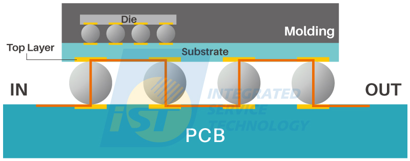
Figure 2: Daisy Chain design of Level 3, connecting the solder balls to the PCB through wiring on the top layer of the component substrate. (Source: iST)
Level 2: Since Level 3 design only involves the top layer wiring of the component substrate, it may not simulate certain failures in complex multi-layered substrates. By extending the wiring from the bottom of the component to the inner layers of the substrate (Figure 3), it allows for further assessment of potential failures such as inner layer wire fracture or delamination caused by external stress.
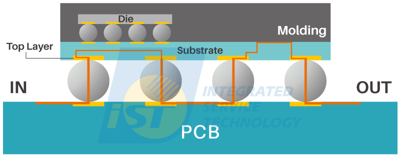
Figure 3: Daisy Chain design of Level 2 extends the wiring from the bottom of the component into the inner layers of component substrate. (Source: iST)
Level 1: Continuously extend the wiring into the internal of the component and connect the surface metal layers of the internal chips to observe the solder joints within the component (Figure 4). According to iST’s observation, this type of Daisy Chain design is being increasingly accepted by more customers. The reason behind this is that as process capabilities improve and the number of stacking layers increases, the solder joints within the component are subjected to greater thermal and mechanical stresses.
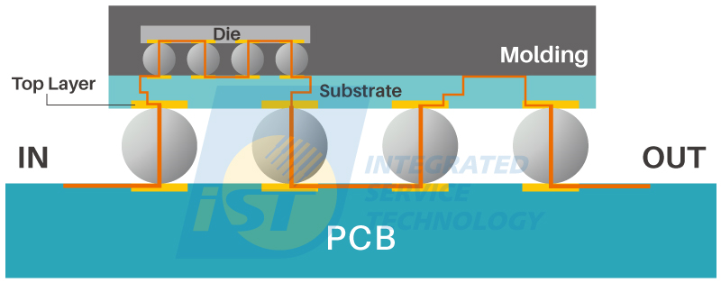
Figure 4: Daisy Chain design of Level 1, with continuous wiring extending to the internal of the component, connecting to the surface metal layers of the internal chips. (Source: iST)
Level 0: This design is the most complex, extending the Level 1 design to the internal chips (Figure 5). Due to the involvement of wafer design processes, choosing Level 0 design will significantly increase costs. In addition, real-time BLR detection devices primarily operate using low impedance and low current methods for quick detection. However, this design often results in higher impedance within the internal chips, which may exceed the specifications of the detection devices and prevent real-time detection. These factors should be considered before designing.
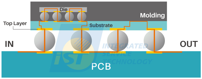
Figure 5: Daisy Chain design of Level 0, extending the Level 1 design to the internal chips. (Source: iST)
2. PCB Design Before Verification
Understanding the Daisy Chain design of component, we now move on to discussing the PCB design. PCB design plays a significant role in the BLR lifespan. The number of layers in a PCB directly affects its thickness. Whether the PCB is thick or thin does indeed impact the test results.
In the Testing environment of temperature cycling, the overall system undergoes thermal expansion and contraction, causing repeated thermal fatigue on the solder joints, eventually leading to fractures. If the PCB can undergo consistent deformation in the same direction as the components during thermal expansion and contraction, it can increase their lifespan. Therefore, when designing a PCB, it is recommended to consider its compatibility with the components (Read more: Count Warpage Amount Before SMT to Avoid Solder Empty and Early Failure).
AEC also considers the diversity of environments in which components are ultimately used, making it difficult to have fixed specifications for PCB layer count and thickness. Therefore, AEC does not impose mandatory requirements, allowing suppliers to design PCBs in a way that is closer to the actual conditions. This approach enhances the authenticity of product data collection. In cases where suppliers are unable to obtain PCB specification information, AEC provides a set of PCB design guidelines for reference. Among these, the recommended option is an 8-layer PCB with a thickness of 1.6mm.
3. Introduction to Automotive Reliability Testing Method - Temperature Cycling Testing
(1) Test Purpose: To understand the characteristics of the component rather than to validate it
Once the component and PCB design are completed, the testing conditions come into play. AEC-Q007 introduces temperature cycling as the first verification method. Here, it is important to pay attention to the purpose section of the specification, which states the purpose is to collect distribution data on the BLR thermal fatigue life of the components. This indicates that the verification aims to gather information for sample failure analysis, which differs slightly from the typical conditions used in BLR testing. In general, BLR testing, the standard is typically set at 500 or 1000 cycles, and passing this cycle indicates that the product has “passed verification.” However, in the case of AEC-Q007, the test purpose is to “understand component characteristics” and collect data for future user reference. The focus is more on gathering information rather than a pass/fail determination based on a specific cycle count.
(2) Test Conditions: Divided into 4 Levels
The temperature cycling test conditions are categorized based on the AEC-Q100 component temperature grades, with a total of 4 grades, where grade 0 represents the most stringent conditions. Ideally, the selected temperature conditions should be equal to or greater than the expected application operating temperature range (see Table 1 for reference). The monitoring process and determination method are referenced from IPC-9701, with recommended dwell times of 10 to 15 minutes for high and low temperatures. Additionally, the specification also mentions that the temperature cycling equipment should not employ rapid temperature ramp rates, such as dual-chamber thermal shock or liquid bath temperature shock.
Table 1: Temperature cycling conditions parameters.
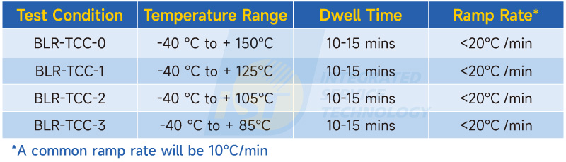
(Source: iST)
(3) Number of Test Samples
The recommended quantity of test samples for preparation should be no less than 50+5 units, including those for failure analysis. It is suggested to continue the testing until 63.2% of all test samples have failed. If no failures occur after a certain period, the test can be terminated at 3000 cycles. AEC-Q007 mentions that in addition to collecting failure information, it is necessary to perform failure analysis on the failed samples and record the failure locations. For BGA components, the specification defines 10 failure locations. If no failures occur during the verification process, it is also recommended to remove samples for cross-sectioning or dye and pry test every 500 cycles.
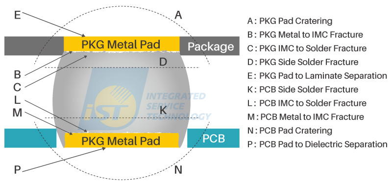
Figure 6: Failure locations of solder joints. (Source: iST)
(4) Definition Parameters for SMT
In addition to component design and test conditions, AEC-Q007 also defines setting parameters for Surface Mount Technology (SMT). Since the results of SMT can affect the reliability data, voids are formed within the solder joints after SMT. Although there are specified standards for voids, both excessive and insufficient void sizes can lead to differences in subsequent reliability data. The specification also recommends that SMT setting parameters should closely resemble the actual production conditions of the supplier. For more detailed information, please refer to AEC-Q007-002.
AEC-Q007 marks the first step in extending the specifications beyond the component itself and incorporating PCB verification methods. Currently, the specification focuses on temperature cycle testing. This is because automotive components face various temperature challenges in real-world applications, such as outdoor environments, different latitudes, and proximity to heat-generating areas (e.g., the engine compartment). Compared to consumer-grade components, automotive components need to overcome more temperature-related factors to ensure reliability. Therefore, “temperature” is one of the key factors that need to be addressed for automotive components.
Based on iST Reliability Verification Laboratory’s long-term observations in BLR, it is indeed possible for solder joints to occur defects under prolonged temperature conditions. The focus on temperature as a starting point in AEC-Q007 is appropriate, particularly when considering the safety aspects of automotive components. In the future, it is expected that AEC-Q007 will continue to introduce additional verification items such as mechanical shock, vibration, humidity testing, and more, in order to establish a comprehensive verification process. Please stay tuned for further updates and information in the iST classroom.
This is to share knowledge and experiences of iST with you. Should there be any inquiry or if you would like to know more about the aforementioned techniques, just ring Chiahao (Mr. Chuang) at +886-3-579-9909 Ext. 6403 or email him at web_BLR@istgroup.com、marketing_tw@istgroup.com