Issued Date:2022/8/2 Materials Bonding Stress
Issued By:iST
Ensuring the reliability of heterogeneous component integration and measuring adhesion and bonding strength between materials
The rise of emerging technologies like 5G and AI has triggered the continuing miniaturization of semiconductors and higher requirements for packaging. As a packaging technology with high chip integration capability, heterogeneous integration is considered the momentum that drives the development of the semiconductor industry in the post Moore’s Law era. Heterogeneous integration means packaging two or even more heterogenous active and passive electronic components in one system, i.e. system in a package (SiP).
However, packaging different types of materials also brings forth various challenges. For example, the choice of underfill will affect the reliability of heterogeneous component integration in flip chip package (FCP). At iST’s reliability verification and analysis lab, filler settling, void, and warpage are the commonly found failure modes in heterogenous integration. So, capturing the rheological characterization of underfill can help optimize the process. (Further reading: How to Eliminate Underfill Voids with Vacuum Pressure Oven)。Materials Bonding Stress
Additionally, mechanical surface characterization and adhesiveness between heterogeneous materials will affect component reliability. At this session of iST Classroom, we and Anton Paar Taiwan will introduce how to use analysis tools to verify the rheological characterization of materials underfill in heterogeneous component integration, as well as the strength of bonding strength of copper and dielectric materials ( Materials Bonding Stress ).
Materials Bonding Stress
I. Measuring the rheological characterization of underfill: Dynamic Shear Rheometer (DSR)
Material rheological characterization aims to describe the rheological and deforestation behavior of materials under stress. To a fluid, viscosity is often used to express the flowing difficulty of fluids under stress, while viscoelasticity is often expressed in terms of storage module and loss module. The dynamic shear rheometer (DSR) can be used to run the related tests.
Materials are placed in a system with well-defined geometric shapes (e.g. cone plate viscometer, concentric cylindrical system). A precision motor control system provides the default stress to measure the shear response of generated in the material under test. Then, we can obtain the relevant rheological characterization, including storage modulus, loss modulus, or damping factors. Additionally, as a rheometer can be used with different temperature control systems, besides discovering the native properties of materials, the rheometer can be used to simulate the changes in rheological behavior of materials under stress in the process.
In the FCP process, the underfill is used to fill the voids between chips and the substrate. Generally, it is made with epoxy, and silicon particles are added to lower the filler’s coefficient of thermal expansion. First, epoxy is spread along the chip’s edges. Through the capillary action, materials automatically infiltrate through the materials to the bottom of the flip chip. Then, it is heated for solidification.
To reduce process lead-time and increase productivity, new generation underfill becomes less viscous. However, this method brings negative effects to the suspension stability of additives which settle more easily in less viscous materials. So, how to overcome filler settling and reduce voids has become an important issue.
Below shows the rheological characterization of 3 different types of underfill measured with the rheometer. Figure 1 shows the viscosity curve of the 3 different types of underfill. The results show that the rheological characterization of these 3 types of underfill are very different. Underfill A is the Newtonian fluid, and Underfill B and Underfill C present the shear thickening (dilatant) behavior under high shear force. Additionally, yield stress is present in all 3 types of underfill.
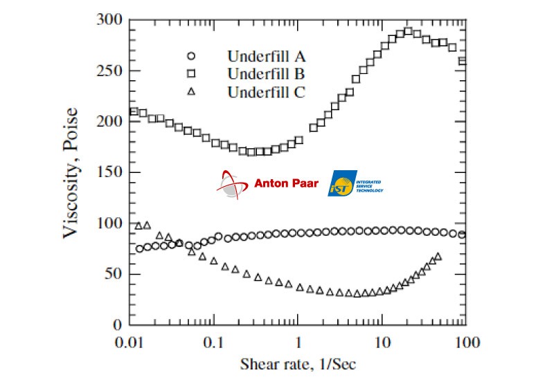
Figure 1: The viscosity curves of 3 different types of underfill at 25°C.
(Ref: Microelectronics Reliability 47(12):1958-1966)The experiment results concluded that the quantity of additives added in underfill has significant effects on the rheological behavior of fillers. Figure 2 shows that the Newtonian fluid behavior is presented when the quantity of additives is below 40%. By adding additives to over 60%, the shear rate changes alongside the viscosity changes of underfill. When the quantity of additives is over 73% and the shear rate is >5 1/s, viscosity increases together with the shear rate increase to present the shear thickening (dilatant) behavior. Additionally, underfill with yield stress and quick fluidity can reduce the likelihood of filler settling.
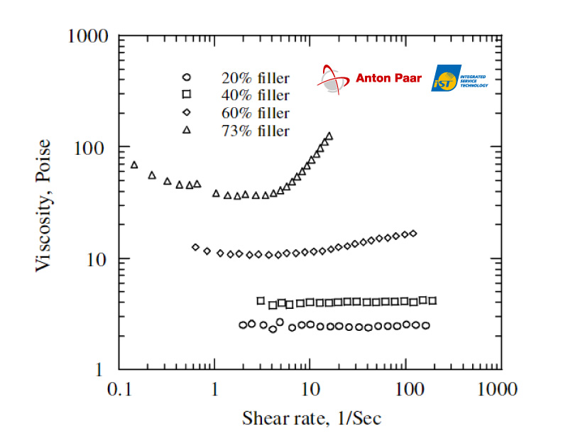
Figure 2: Effects of additive quantity on underfill rheological characterization.
(Ref: Microelectronics Reliability 47(12):1958-1966)II. Measuring adhesion and bonding strength between heterogeneous materials-indentation/scratch tester
Heterogeneous integration involves combining together materials of different characterization. So, the adhesive and bonding strength between materials are two critical factors affecting component reliability.
The indentation test is a method that can precisely measure the mechanical characterization of films, coatings, and blocks, whether materials are soft, hard, brittle, or ductile. Its mechanical characterization including hardness, elastic modulus, elasticity, plastic work, and creep can all be obtained.
Traditionally, the indentation test adds load to a known geometric-shaped indenter to press on the material surface to calculate material hardness based on the area of deformation caused by the indentation. However, as the mark is tiny in micrometer and nanometer scales, it is difficult to accurately measure the area of the mark, and the traditional indentation test will be unable to measure material hardness in micrometer/nanometer scales.
So, micrometer/nanometer indentation testers are equipped with precision stress and depth sensors to precisely control the loading and unloading processes of the indenter and record the load and indentation depth at the same time. Figure 3 shows the continuous load-indentation depth curve. With the theoretical model, we can calculate a material’s mechanical characterization.
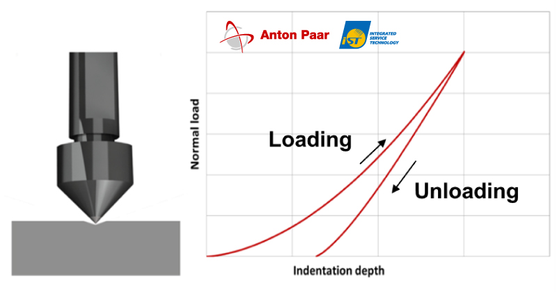
Figure 3: Continuous load – Indentation depth illustration
(Ref: Anton Paar presentation)Additionally, the scratch test is a generally accepted method to measure adhesion, bonding strength, and scratch resistance of coatings.
A known-shaped diamond indenter is pressing against the surface of DUT. When the DUT moves at the default speed, the indenter will leave scratches (as shown in Figure 4) on the DUT’s surface. By applying a constant load throughout the indention process, we can measure the scratch hardness or resistance of the tested material. By progressively increasing load during the indention process, we can record the changes in the normal force and friction, indention depth, and sound wave signals in the process at the same time to understand the material’s adhesiveness.
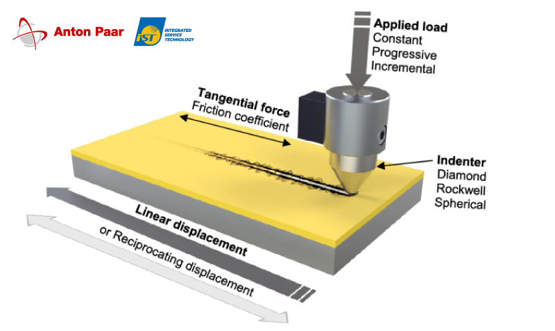
Figurer 4: Illustration of the principles of scratch tester.
(Ref. Anton Paar presentation)Studying the adhesiveness between heterogeneous materials with the scratch tester has been widely applied to the automotive industry and panel industry. For example, Figure 5 shows testing the scratch resistance of a smartphone display with the scratch tester. The panel contains an aluminum oxide coating of about 100nm thick. In the experiment, a 2μm-raidus Sphero-conical indenter is used, with a maximum load of 50mN.
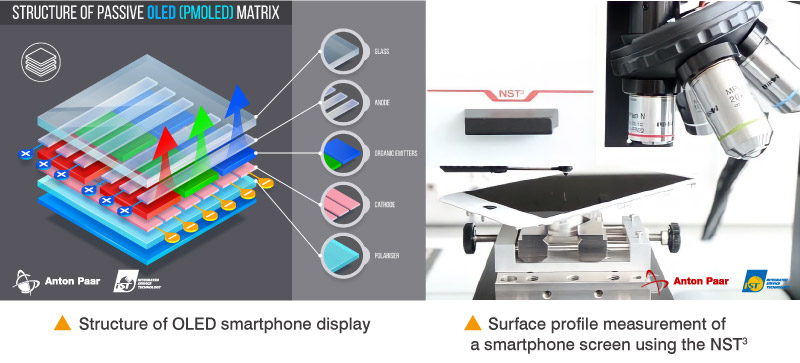
Figure 5: Scratch resistance test of the 100nm-thick aluminum oxide coating of smartphone display.
(Ref: Anton Paar application report: Mechanical surface characterization of smartphone displays)Figure 6 (left) shows the scratch on the display and its failure mode. Figure 6 (right) shows the changes in the normal force and indentation depth (Pd), residual depth (Rd), and friction coefficient (CoF). At the threshold load position (roughly 44mN), the coating failure and significant changes in Pd, Rd, and CoF are observed. If a coating with better adhesiveness is desired, the greater the threshold positions the better.
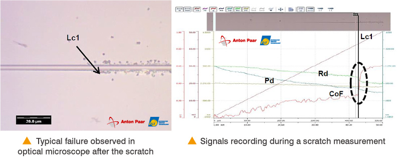
Figure 6: Results of the scratch test of the 100nm aluminum oxide coasting: (left) Image of the scratch failure observed from OM, and (right) signals of force and displacement.
(Ref: Anton Paar application report: Mechanical surface characterization of smartphone displays)III. Calculating copper mechanical characterization in 3D package TSV
3D package is an important technique to achieve heterogeneous integration. In 3D package, the through-silicon via (TSV) is the major technique to realize chip vertical integration. A completed TSV structure contains many material interfaces. The diffusion effect of copper and the size of copper grains in the TSV have significant effects on copper mechanical characterization. So, correct development of copper mechanical characterization in TSV can benefit the reliability analysis and design of the TSV structure.
To obtain the elastic modulus of TSV-Cu, a nanoscale indention tester with a Berkovich indenter is used in a nanoscale indentation test performed near the center position of the exposed TSV-Cu surface. The indentation depth is 500nm. The material’s elastic modulus and hardness are tabulated below:
Table 1:Elastic Modulus E and Hardness H of TSV-Cu
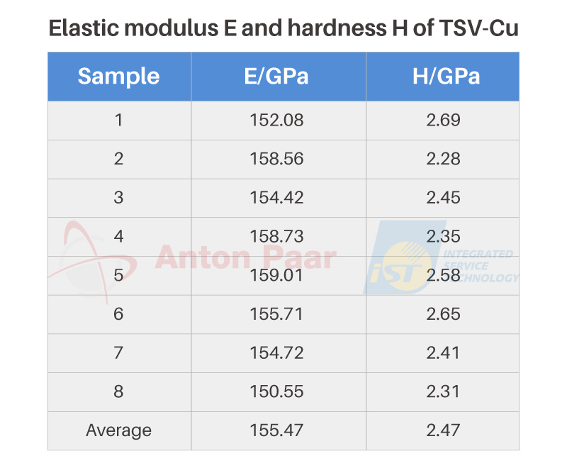
By combining these results with the finite element method can further infer the materials stress-strain curve. Figure 8 shows the calculated TSV-Cu elastic module, strain strength index, and yield strength is 155.47 GPa, 0.4892, and 47.91 MPa respectively.
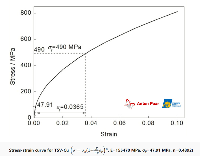
Figure 7: TSV-Cu stress-strain curve.
(Ref: 2014 《金屬學報》 50 (6): 722-726 )IV. Effects of the solidification temperature on surface hardness of dielectric material (PBO)
Fan-out wafer level package (FOWLP) is a novel packaging technique. In this process, the redistribution layer (RDL) is a key step. In FOWLP, RDL is generally composed of dielectric materials (PI, PBO) and copper (Cu). If products of higher reliability are needed, a strong adhesiveness between the dielectric materials and Cu is required in order to resist the high-temperature and high-humidity tests in the reliability test. So, in this example, the nanoscale indentation test can be used to understand the effects of different solidification temperatures on material hardness. In this experiment, a Berkovich indenter was used, with a maximum indentation depth of 500nm, to analyze PBO at different solidification temperatures. The results show that PBO hardness remained unchanged at the beginning when the temperature rose and began to reduce (as shown in Figure 8) from 225°C onwards. Besides understanding PBO’s mechanical characterization, the adhesiveness of Cu and dielectric materials on RDL can be measured with the scratch tester in the future in order to optimize the manufacturing process.
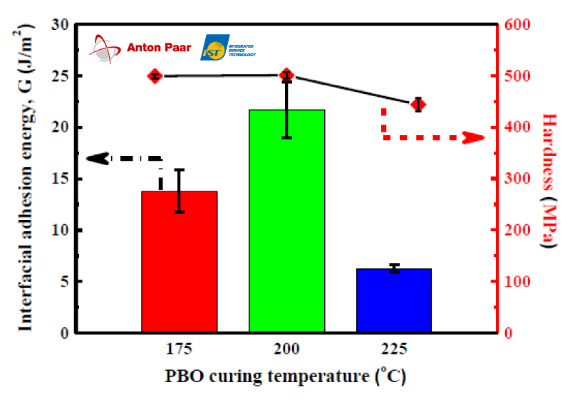
Figure 8: Correlations between solidification temperature changes and surface hardness of PBO.
(Ref: Effect of dielectric process on the interfacial adhesion of RDL for FOWLP, 2377-5726/20/$31.00 ©2020 IEEE)
At the development of the product technology for advanced heterogeneous integration packaging, besides the abovementioned materials analysis techniques, iST laboratory also offers technical support for reducing the likelihood of void occurrence with underfill. With years of experience in testing the adhesion between metals and dielectric materials with the linear four-point probe (van der Pauw method), besides helping customers to test the mechanical characterization of materials, we can complete all product certification tests by combining thermal property, reliability, and lifetime tests. When faults and failures occur after the high-temperature, high humidity, or vibration test, it is necessary to find the factors causing product faults for the reference of materials fine-tuning or process adjustment. So, if you want to shorten the lead-time of product development and cut equipment costs, iST have a range of total solutions to provide you with the above material analysis, reliability verification, and failure analysis services to meet your specifications and needs.
If you need our services or are interested in learning more about the relevant knowledge, please feel free to contact Mr. Chang at +886-3-579-9909 ext. 6613 or by email to SA_TW@istgroup.com , marketing_tw@istgroup.com
Reference:
- 1. 納米壓痕法確定TSV-Cu的應力-應變關係;秦飛,項敏,武偉;北京工業大學機械工程與應用電子技術學院, 北京100124, 2014 《金属学报》 50 (6): 722-726 https://www.ams.org.cn/article/2014/0412-1961/0412-1961-50-722.shtm
- Effect of dielectric process on the interfacial adhesion of RDL for FOWLP, 2377-5726/20/$31.00 ©2020 IEEE
- Mechanical surface characterization of smartphone displays, Anton Paar XCSIA086EN-A.
- The effects of rheological and wetting properties on underfill filler settling and flow voids in flip chip packages, Microelectronics Reliability 47(12):1958-1966.
Author:
安東帕公司、宜特科技股份有限公司