Issued Date:2022/4/26MTTF
Issued By:iST
Have you been asked to provide MTTF and λ by end-customers after HTOL?
How to interpret and use MTTF and λ?
What are the differences between MTTF and MTBF?

When advanced packaging technologies such as system in a package (SiP), system on a package (SoP), package on a package (PoP), three dimensions (3D) and 3D through-silicon via (TSV) are trending, chips of different materials and features are integrated into one package. While the materials contained in components packaged with these methods are rather complex and comprehensive, reliability life prediction has become one of the focus of various manufacturers at the moment.
To help customers verify product reliability life prediction, iST offers the High Temperature Operation Life test ( HTOL) to help IC design houses run the reliability life prediction of chips made with advanced processes or advanced packaging in a simpler and more cost-effective way. Over the last decade, many customers have asked our reliability verification lab the following questions: How to interpret and use the values from HTOL and the resulting Mean Time To Failure (MTTF) and Failure Rate (λ)? What are the differences between Mean Time To Failure (MTTF) and Mean Time Between Failure (MTBF)? What parameters should be used?
In this session, the iST Classroom will show you how to resolve these problems in an easy-to-understand approach.
MTTF
HTOL is part of the Operating Life Test (OLT).
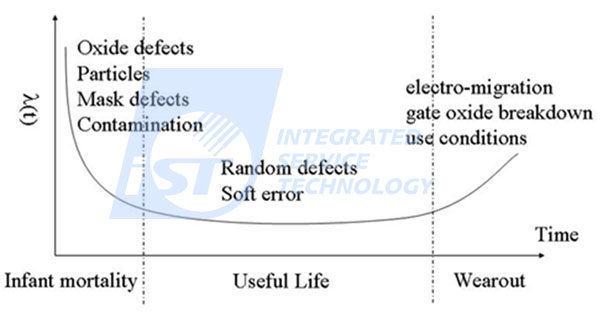
The Operating Life Test (OLT) of IC simulates a long-period of work environment with accelerated temperature and voltage alterations in a short period of time, in which the bathtub curve is divided into 3 sections namely Infant Mortality (Early Life Failure), Useful Life, and Wear Out. Different test methods are applied for different failures.
1. What are the differences between Mean Time To Failure (MTTF) and Mean Time Between Failure (MTBF)? How to use them?
Both MTTF and MTBF are standards for predicting reliability life. They are different in a way that MTBF is for products that are recoverable or expensive in the unit cost (e.g., computers, airplanes, cars), while MTTF is used for products that are irrecoverable or cheaper in the unit cost (e.g., ICs, semiconductor components)
- MTBF (Mean Time Between Failure) refers to the average interval between failures. It is often used for system products and is usually applied to find the average operating time between two consecutive failures.
- For example, a computer server is a system integrating multiple products, including the power supply unit (PSU), motherboard (MB), hard disk drive (HDD), graphics card (VGA), memories (RAM) and others. If the PSU fails, the computer server (system) will also fail ( stop working). After restoration and operating for some time, the system server can fail again due to a RAM anomaly. In this case, the interval between the two failures (PSU and RAM) can be called the MTBF of this computer server.
- MTTF (Mean Time To Failure) refers to the average time to failure. It is different from MTBF in that it is often used for irrecoverable products, such as ICs, whose designated functions after failure are irrecoverable through maintenance and repair.
- For example, an IC will fail after long-time use due to electromigration and ageing and this IC cannot be restored through maintenance and repair and must be replaced directly.
2. After running the HTOL and calculating MTTF (Mean Time To Failure) and λ (failure rate), how to use the outcomes?
After the iST lab helps you run HTOL, your end-customers often ask you to calculate the MTTF and λ values. How to calculate them?
We can calculate these values with reference to the formula in the JEP001-3A provided by the Joint Electron Device Engineering Council (JEDEC).
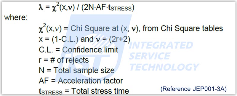
In the following example, the lab conditions are as follows:
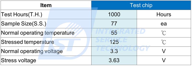
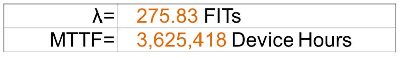
After the experiment, if the sample’s failure count is 0 with the confidence level of 90%, the average failure rate λ and reciprocal MTTF are:
Continuing with the above calculations, how to use them? Are they good or bad?
First, we need to understand the definitions of λ and MTTF. It is very difficult to calculate the short-time failure rate and it is also less meaningful. Hence, we prefer to calculate the average failure rate in a given time interval, e.g., 1,000 hours/one month or one year as the time unit. In general, the results are presented this way: Average failure level (λ) = Total failures in the interval / Total operating hours (Total operating hours = total samples x operating hours). As the failure rate is very low, we will express it in failures in time ( FIT = 10-9). MTTF is the reciprocal of λ, i.e., the average time leading to the failure. However, please note that instead of hours, Device Hours is the unit for MTTF.
Then, with reference to the calculation of cumulative distribution function (CDF) in JESD74A:
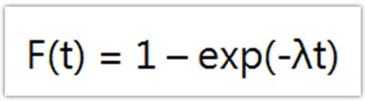
After inputting the required prediction time in this equation, we can calculate the predicted group cumulative failure rate at different times.
Figure 1 below shows the predicted group cumulative failure rate at different periods. For example, the group cumulative failure rate is 1.2% in 5 years and 2.39% in 10 years. With these values, you can compare if a product meets the requirements of end-customers or the level of acceptance of your company.
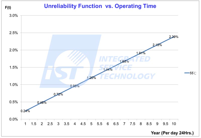
Figure 1 Statistics on group cumulative failure rate.
3. How to find the testing conditions of reliability life with MTTF(Mean Time To Failure) or λ (failure rate) using backward calculation?
After understanding the conversion among MTTF, λ and cumulative failure rate and receiving the testing requirements of end-users, we can design suitable testing conditions based on these requirements.
In the following example, the required result is a failure rate below 1% for 10 years (24Hrs a day).
First, after calculating CDF,
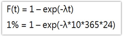
we can see that λ≦114 FITs will meet the requirement.
Based on this target, we can match with other experiment conditions, such as how long the test takes, how many samples the test needs, the voltage and temperature required to boost stress to what extent, the number of accepted failures, the targeted failed model…
Table 1 below shows the three sets of reliability test conditions. The outcomes of each set can meet the requirement λ ≦ 114 FITs, i.e., the initial requirement of end-customers. The adjustable parameters are composite. Fine-tuning based on the ambient conditions is advised in designing reliability experiment conditions to design the experiment conditions that meet the ambient requirements.
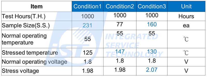
Table 1 Three Sets of Reliability Test Conditions
In this article, we share the experience in reliability test with you, a long-time supporter of iST. As Asia’s largest third-party verification and analysis lab, with sufficient field experience, iST offers the most complete and perfect equipment distribution and technical consultation services, ranging from the planning of initial experiment conditions to detailed environments; the design of reliability tests for hardware assessment, circuit and layout design; and the test for hardware production and manufacturing, to subsequent reliability test implementation and anomaly analysis and elimination. Our services can help you quickly and accurately run various reliability test requirements and provide you with consultation services for various products, such as consumer electronics and automotive electronics.
If you have doubts on the Reliability test, you are welcome to contact Mr. Diaw Tseng at +886-3-579-9909 ext. 6417 / Mr. Haoyu Lin ext. 6417 or write to us at web_cre@istgroup.com or marketing_tw@istgroup.com
Other services you may be interested in
MTTF