Issued Date:2020/2/4 MIM capacitor
Issued By:iST
In case of a MIM capacitor anomaly, how to pinpoint the defect with a failure analysis tool?
MIM capacitor
MIM (Metal-Insulator-Metal) capacitors are widely adopted in screening out noise from RF-IC, serving as load components in digital electronics and general used in IC and PCB applications. In case of any MIM capacitor leakage current, deformation or other anomaly the ICs containing them may fail to perform or even result in delamination.
Nonetheless, these MIM anomalies are hard to pinpoint as they tend to be covered by the metal layer.
Conventional failure points can be detected in two ways. The one is to delayer the MIM samples to the vias (interface between metals) then observing it with a scanning electron microscope (SEM).This method is valid for checking failure of Via but not points neighboring it.
The other is to identify the defects with EBAC (Electron Beam Absorbed Current). This method suffers when the lower plate of MIM samples are not earthed.
How to pinpoint the defects of MIM? There are five simple steps employed by iST. See the following typical cases of iST’s detecting MIM leakage current with these five steps.

Step 1: I-V Curve Measurement
Check leakage current of MIM capacitor with I-V Curve.
Step 2: IC Delayer
It’s hard to directly pinpoint failure point with OBIRCH or other electrical characteristics measurement tools once leakage current detected as the MIM capacitor is capped with a metal shield. Instead, the metallic cover atop MIM shall be delayered in advance.
Step 3: Coating Pads
Once the MIM delayered and pad coated with FIB circuit editing technique, power it on and feed in signals to find the defects (figure 1).
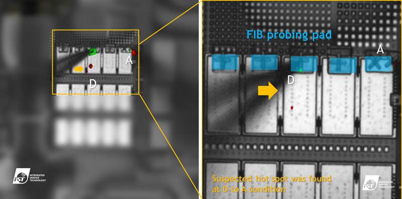
Figure 1: Location of defect (hot spot) is red marked
Step 4: Dual Beam FIB
Observe cross section of samples at abnormally hot spots with a Dual Beam (FIB) tool (Figure 2).
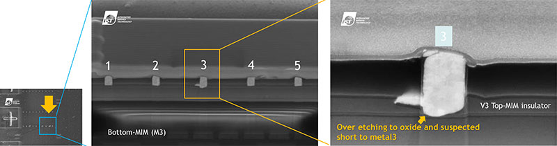
Figure 2: Abnormal MIM structure found at the bottom of Via 3 by DB-FIB
Step 5 :Imaging (TEM)
It is finally identified by transmission electron microscope (TEM) that the insulation layer of MIM failed and resulted in a leakage path between the upper and lower plates. The cause to leakage current is now identified (Figure 3).
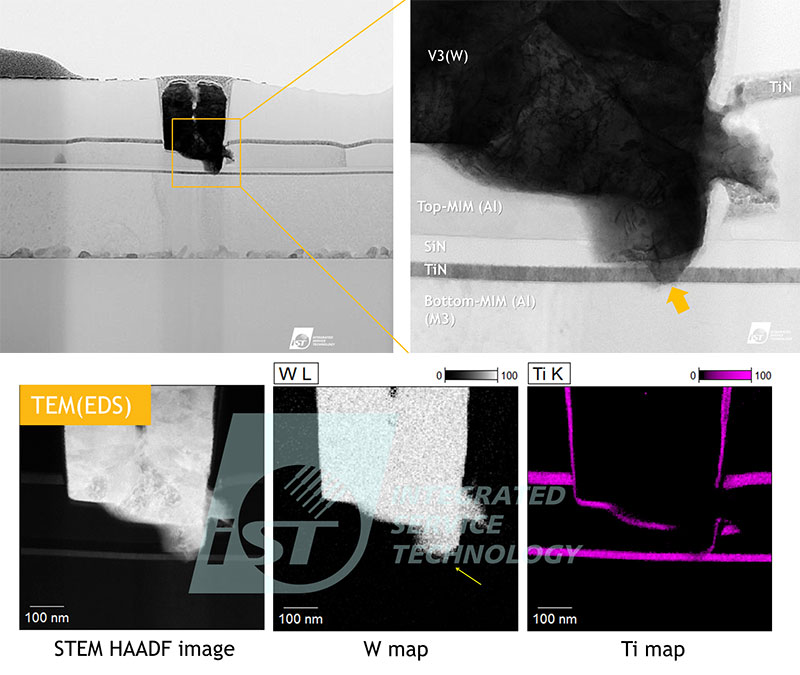
Figure 3: The insulation layer of MIM failed and resulted in a leakage path between the upper and lower plates
To learn more about our services, just ring Mr. Shih at +886-3-579-9909 EXT 6775 or email us at web_ise@istgroup.com.